I.B. 32-255-1G
Page 19
Effective 12/02
To remove the circuit breaker from the structure,
reverse the procedure just described by turning the lev-
ering-in crank in a counterclockwise direction. Keep in
mind that safety interlocks may cause the circuit breaker
to open and/or springs to discharge during the removal
process. It depends on what condition the circuit break-
er was in as removal began.
For additional information on the levering mechanism,
refer to paragraph 5-6 in this manual.
4-8.2 OPERATION CHECK PERFORMANCE
Move the circuit breaker to the TEST position and
engage the secondary contacts following the procedure
described in paragraph 4-8.1. As soon as the closing
springs are charged, the condition will be indicated by a
Spring Charged/Discharged Indicator on the front of the
circuit breaker (Figure 3-5). In addition, the status of the
main contacts, open or closed, is indicated on the front
of the circuit breaker.
Close and trip the circuit breaker several times to verify
closing and tripping operations. Conclude by closing the
circuit breaker. The circuit breaker is now closed in the
TEST position with springs charged.
Figure 4-3 Engaging Extension Rails in a Lower Circuit
Breaker Compartment
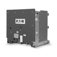
Figure 4-4 Typical VCP-W Circuit Breaker Bottom View
➀ Ground Contact
➁ Secondary Disconnect
➂ Close Floor Tripper
➃ Levering Latch
➄ Trip Floor Tripper
➅ Code Plates
➆ MOC Operator
➇ TOC Operator
➀
➆
➄
➇
➁
➂
➃
➅
 Loading...