Eaton 9395XC UPS 1200kW/1200kVA, 1350kW/1350kVA or 1500kW/1500kVA 164001079—Rev 01 xiii
LLiisstt ooff FFiigguurreess
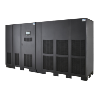
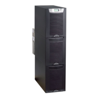
Figure 1. Eaton 9395XC UPS (LD)...................................................................................................................2
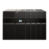
Figure 2. Eaton 9395XC UPS (HD) ..................................................................................................................3
Figure 3. UPS Cabinet Dimensions – HD (Front View)....................................................................................... 16
Figure 4. UPS Cabinet Dimensions – LD (Front View) ....................................................................................... 17
Figure 5. Cabinet Dimensions (Right Side View) .............................................................................................. 18
Figure 6. ISBM/PM Section Dimensions – (Front View)..................................................................................... 19
Figure 7. ISBM/PM Section Dimensions – (Top View)....................................................................................... 20
Figure 8. UPS Bottom View ........................................................................................................................ 20
Figure 9. I/O Section Dimensions – HD (Front View)......................................................................................... 21
Figure 10. I/O Section Dimensions – (Top View)................................................................................................ 22
Figure 11. UPS Center of Gravity – HD (Front View) ........................................................................................... 23
Figure 12. UPS Center of Gravity – LD (Front View)............................................................................................ 24
Figure 13. Remote EPO Switch Dimensions .................................................................................................... 25
Figure 14. UPS Cabinet as Shipped on Pallet (ISBM/PM Section) .......................................................................... 38
Figure 15. UPS Cabinet as Shipped on Pallet (I/O Section)................................................................................... 39
Figure 16. Removing the ISBM/PM Section Left Side Shipping Bracket ................................................................. 43
Figure 17. Removing the ISBM/PM Section Right Side Shipping Bracket................................................................ 44
Figure 18. Removing the I/O Section Left Side Shipping Bracket .......................................................................... 45
Figure 19. Removing the I/O Section Right Side Shipping Bracket......................................................................... 46
Figure 20. UPS Forklift Locations................................................................................................................... 47
Figure 21. I/O and ISBM/PM Electrical Access.................................................................................................. 49
Figure 22. Section Bottom Entry Landing Conduit Plate ...................................................................................... 50
Figure 23. UPS Intercabinet Power Terminal Locations....................................................................................... 51
Figure 24. I/O to ISBM/PM Section Joining ...................................................................................................... 53
Figure 25. I/O Section to ISBM /PM Section Joining Strap................................................................................... 54
Figure 26. I/O and ISBM/PM in Position .......................................................................................................... 55
Figure 27. ISBM and ISBM/PM Section Debris Shields....................................................................................... 56
Figure 28. ISBM and ISBM/PM Section Conduit and Wire Entry Locations.............................................................. 57
Figure 29. I/O Section Power Terminal Locations .............................................................................................. 58
Figure 30. I/O Section Power Terminal Detail AA............................................................................................... 59
Figure 31. UPS Power Terminal Detail BB........................................................................................................ 61
Figure 32. ISBM Section Interface Terminal Locations........................................................................................ 63
Figure 33. Minislot Wire Entry....................................................................................................................... 64
Figure 34. Typical Alarm Relay Connection....................................................................................................... 66
Figure 35. Terminal Blocks TB1, TB2, and TB3 Connector Assignments................................................................. 67
Figure 36. Typical Battery Interface Connection ................................................................................................ 68
Figure 37. Minislot Communication Bays......................................................................................................... 69
Figure 38. REPO Switch .............................................................................................................................. 70
Figure 39. Normally-Open REPO Switch Wiring ................................................................................................ 71
 Loading...
