Eaton 93PM Emergency Lighting UPS (50 kW, 480V Three and Four-Wire UL 924) Installation and Operation Manual P-164000569—Rev 03 69
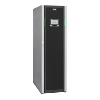
Figure 45. UPS Control Panel
The control panel consists of:
• A color liquid crystal touch screen display (1).
• A horizontal row of status indicators (2). See paragraph 7.2.1 Status Indicators.
The following paragraphs describe using the UPS control panel to monitor the UPS. See paragraph
7.3 Single UPS Operation for use of the operational controls.
When the unit powers up, the screen displays the as shown in Figure 45.
77..22..11 SSttaattuuss IInnddiiccaattoorrss
The four symbols on the bottom of the control panel are status indicators. These colored light emitting diode
(LED) lamps work with the alarm horn to provide the operating status of the UPS.
Table 14 describes the status indicators.
Table 14. Status Indicators
Indicator Status
Description
Green
On The UPS is in Double Conversion mode. The power module is supplying power to the
critical load.
Off The UPS is turned off.
On The UPS is in Battery mode. Because Battery mode is a normal condition of the UPS, the
normal indicator also remains illuminated.
On The UPS is in Bypass mode. The critical load is supported by the bypass source. The normal
indicator is not illuminated when the system is in Bypass mode.
UPS Operating Instructions

 Loading...