INM MTL 130-0175 Rev 4
5
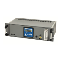
3.3 Electronic unit connections
The following points should be observed for the wiring between the sensor/reactor unit and the
control/display electronics.
• The cables should avoid as much as possible tracking other high current cables.
• The signal outputs may be connected using standard instruments cable (e.g. 7/0.2). All
signal outputs are short/open circuit proof.
• If the cables are extended only use wire of similar type and current carrying capacity.
The thermocouple wire pairs 3&5 and 14&16 must use Type K thermocouple extension
or compensating cable.
WARNING
It is strongly recommended that the Temperature Error volt-free contacts
(terminals 10 and 11) are used to activate a sample cut-off in the event that
excessive sample flow (greater than 250ml/min) causes the catalyst to over
heat. Typically the contacts would be used as a logic input to the overall
burner controller. The controller would apply a delay to the burner shut-off
command so as to avoid shutting the burner down in a transient temperature
error situation.
120-0645/1
A.C. + -
13 14 15 16
A.C. + + NC+
- - -
1 2 3 4 5 6 7 8 9 10 11 12
Fuse Ty pe ‘T’ 1.6A
20mm x 5mmØ
F USE
230
Set A.C. supply voltage
here
before
applying power to
(Re-wirable plug
supplied)
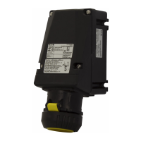
AC
Mains Connector
Via cable glands in enclosure
Sensor Heater
Sensor T/C
Use Type K Comp cab le
Sensor Signal
Analogue O/P
Temperature Error
(Closed = OK)
Catalyst Heater
Catalyst T/C
Use Type K
Comp cable
Voltage Selector
Ensure this is corr ect
BEFORE powering
 Loading...