AD 33-855-4
Page 33
8.4 Explanation
of Test Procedures
1. Defeat
(Short
Out)
Zone lnterlocks
.
Ground
Fault time and Shoft
Delay
time
will be at
the minimum values during
testing, if not defeated.
.
Use ZSI Shorting
Plug or the
Test Cell
Harness Assembly.
o
Already
included on 510 Basic
Retrofit Kits.
2. Defeat Unpowered
Thermal
Memory
(LTM)
.
LTM automatically
reduces the
time to trip
the Breaker, if not defeated.
.
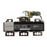
Remove rating
plug
from the Trip Unit.
Jumper
is located at the back
of the Rating
Plug cavity.
.
Move
jumper
to the right
for horizontal
Trip
Units.
Move
jumper
to the bottom
position
for vertical and standard
Trip
Units.
.
lnsed the Rating Plug back
into the Trip
Unit.
3. Defeat
Ground Fault
Trip Function
(Primary
lnjection
Testing Only)
.
Will
trip the Breaker on Ground
Fault
when
testing the Long Delay
trip function,
if not
defeated.
o
Move
the
green
wire
from the
"G" terminal
to the
"N"
terminal
(on
the Auxiliary
CT
Module) before testing
Long Delay, Shod
Delay, or lnstantaneous
(phase
testing).
.
Green
wire must be returned
to
"G"
terminal after
phase
testing.
.
Required
for all Trip Units equipped
with
Ground
Fault
protection.
4, Use Auxilary
Power
.
Provide
power
to the
Trip Unit
for Primary
lnjection, Self
,
and
Secondary
lnjection
Testing.
.
Use
the Auxiliary
Power Module and
plug
it
into the
front
of
the Trip Unit,
or use
Test
Cell
Harness Assembly
and
plug
it into
External Harness.
5.
Reset Trip Unit
(Resetting
Powered Thermal
Memory)
.
lf not reset, the LED
will remain
lit
and
reduce the
Rating Plug's battery
life for 510
Trip
Units.
.
lf not reset, the
Breaker will be
held in the
Trip
Free
condition
and
the LED will
remain
lit for 61 0
to
91
0 Trip Units.
lst Reset
Method
-
With Auxiliary
Power
"On",
press
Trip
Unit's
Reset button.
-
Turn Auxiliary Power
"Off"
for 10
seconds.
-
Turn Auxiliary Power
"On".
2nd Reset
Method
-
With Auxiliary Power
"On",
set
the Test
Amps to
1.
-
Press
and release the
Trip Unit's Test
push
button.
-
Quickly
press
and release
the Trip Unit's
Reset button before
Trip Unit operates.
Reset Trip Settings
.
See
the appropriate
table to apply
the
proper
Trip Unit settings.
7. Abod
Test
Avoid overheating
all the components
during
Primary lnjection
testing.
Avoid overheating
of the Aux. CT
module
and
Trip Unit during Secondary
lnjection
testing.
Speeds up
the testing
process
for a
Self
Test.
Manually
stop the test
per
the
appropriate
table,
if the Breaker does
not trip
(see
"Stop Test After" column).
8. Confirm
Breaker Status
Confirm the Breaker
position
indicator
reads
"OPEN" and
the
spring
charged
indicator reads
"DlSCHARGED".
After
the tests are completed,
change
to
the customer's
Trip Unit settings.
Etfective 9/01
E:T.il
 Loading...
