EasyManua.ls Logo

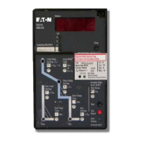
Eaton Cutler-Hammer Digitrip RMS 510 - Resetting the Trip Unit after a; Removing the Breaker from the CONNECT Position

Eaton Cutler-Hammer Digitrip RMS 510
79 pages
To Next Page IconTo Next Page
To Previous Page IconTo Previous Page
Loading...
AD 33-855-4
9.4
Resetting
The
Trip
Unit
After
a
Trip
Followino
an
Overcurrent
Trip.
the
Trip
Unit
is reset
bv deoreisinq
the
TRIP
RESET
push
button'
The
frip
Unit
should
Oe
reset
before
the
Breaker
is
closed.
The
RMS
510
Retrofit
Trip
Unit
mode
of
trip
LEDs
are
powered by
the
Rating
Plug
battery'
The-
.
Breaker
can
be
closed
without
resetting
the
Trip
Unit,
however
the
LED
will
remain
lit until
the
Trip
Unit
TRIP
RESET
push
button
is depressed'
Resetting
the
Trip
Unit
in a
timely
manner
saves
on
battery
life.
ln
new condition.
the
battery
will
power
the
LED
for
approximately
60
hours'
The
RMS
61
O, 810,
&
910
Retrofits
have
provisions
for 120
VAC
source.
lf the
120
VAC
source
is
"ON,"
the
Breaker
will be
held
in
the
Trip
Free Condition
(cannot
be
closed)
by
the
Direct
Trip
Actuator
iDTA)
until
the
Trip
Unit
TBIP
RESET
push
button
is
deoressed.
The Trip
Unit
mode
of
trip LEDs
are
oowered
bv
the
120
VAC
source,
and
backed
up
bv the
batterv
in
the
Rating
Plug.
lf
the
120
VAC
source
to
the
Trip
Unit
is
lost.
the
Trip
Unit acts
as
described
for the
RMS
510.
The
RMS
810
& 910
Retrofits
have
communica-
tions
capability,
which
permit opening
and
(for
electrically
operated
Breakers)
closing
via
-
.
PowewrN-et.
ln
the event
of
an
Overcurrent
Trip,
the Trio
Unit
will
act
as
described.
requiring
local
resetting
of
the
Trip
Unit
before
the Breaker
can
be
closed.-However,
if
the Breaker
is
tripped
remotely
via
PowerNet
(alphanumeric
coded
message
EXfD,
it
can
be
closed
via
PowerNet
without
local
resetting
at
the
TriP Unit'
9.5
Removing
the
Breaker
From
the
CONNECT
Position
RMS
510
Basic
Retrofitted
Breakers
include
no
External
Harness
and
require
no
special
proce-
dures
(other
than
those
normally
observ-ed)
for.
remouing
the
Breaker
from
the
CONNECT
position
in the
Switchgear
Cell.
RMS
510
Zone,
61 0,
81
0, &
9.1 0
Retrofitted
Kits
are
equipped
with an
External
Harness
Care
must
be observed
to disconnect
the
External
Harness
Pluo
from
the Switchgear
Cell
Harness
Assembly
whin
removing
the
Bieaker
from
the CONNECT
position.
NOTE:
lf
the Cell
Terminal
Block,
Wiring
Harness,
and
Plug
Assembly
are
properly
positioned
in
the
Switchgear
Cell
with
respect
to
the
Breaker,
the
Breaker
can
be
withdrawn
to
the
TEST
position with the
External
Har-
ness
plugged
in.
However,
to withdraw
the
Breaker
completely
from
the cell,
the
External
Harness
must
be disconnected'
A
cnurror'r
FAILURE
TO DISCONNECT
THE
EXTERNAL
HARNESS
FROM
THE
CELL
HARNESS
ASSEMBLY
IN
THE
SWITCHGEAR
CELL
COULD
CAUSE
PHYSICAL
DAMAGE
TO
THE
EOUIPMENT.
E:T.ltl
Effective
9/01

Table of Contents

Related product manuals