IB02602004E For more information visit: www.eaton.com
Instructional Literature
Effective: May 2008 Page 27
Instructions for the FP-6000 Protective Relay
“Enter” Pushbutton
The “Enter” pushbutton allows
the user to view the display
menus, which are chosen by the
up/down arrows. It also is used
in the programming mode to
change setting values and save
the settings. Once a setting is
chosen by the up/down arrows,
the “Enter” pushbutton is used
to enter that setting. If the
“Enter” pushbutton is not
pushed when changing a
setting, that setting will not be
changed.
4.4 RS-232 Communications Port / Front Panel
Communication
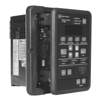
The FP-6000 communications port (located on the bottom right of
the front panel) is a straight through DB9 RS-232 communica-
tions port. It’s used to view the status of the FP-6000 and to
download setpoints via Eaton’s Power Port Communications soft-
ware and a personal computer. It is also used for upgrading firm-
ware using the Flashloader program. PowerPort software can be
obtained from the Eaton Internet site, www.eaton.com/electrical.
The FP-6000 transmits communications on pin 2 and it receives
communications on pin 3, making it a Data Set or Data
Communication Equipment (DSE/DCE) under the definitions of
the RS-232 standard. The FP-6000 does not use the RS-232
hardware control lines. Although the FP-6000 operates with the
“3-wire” connection, a standard off-the-shelf serial cable will
allow communication. See Figure 9 for the DB9 cable
connections. An example of an off-the-shelf cable is the
RadioShack
®
, 26-117B, Male DB9 to Female DB9 Shielded RS-
232C Cable.
See Section 10 for a detailed description of the FP-6000
communications and the Eaton PowerPort software.
Figure 9. RS-232 Cable for 9- and 25-pin D-Subminiature
Connectors.
4.5 Battery for Trip Indication
Beneath the front panel communications port lays a receptacle
for a lithium disc-style battery. The battery is used when there’s a
control power failure to latch the FP-6000 trip state and to
operate the front panel trip LED. The FP-6000 can last 72 hours in
this state on a completely charged lithium battery. When the
FP-6000 is energized, the trip latch and LED indicators are
powered by system power, preserving the batteries capacity.
Figure 10. LED and Test Button Location.
Green “Battery
Test Indicator” LED
“Battery Test”
Button
Green “Battery
Test Indicator” LED
“Battery Test”
Button
Green “Battery
Test Indicator” LED
“Battery Test”
Button

 Loading...


