Instructional Literature
Page 28 Effective: May 2008
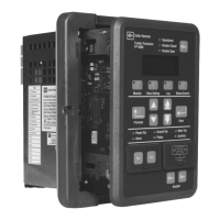
Instructions for the FP-6000 Protective Relay
For more information visit: www.eaton.com IB02602004E
A defective or discharged battery causes the loss of trip state
visual LED indication during power loss conditions. A “Battery
Test” button and a green “Battery Test Indicator” indicating LED
are provided next to the lithium battery receptacle. Standard
periodic maintenance should include pressing the Battery Test
Button and noting that the “Battery Test Indicator” LED turns on,
showing adequate operating capacity in the battery. Battery
failure will not effect relay memory. The battery is for LED
indication only. See Section 2.6 Startup for initiating the battery
into service and Section 11.4 for battery maintenance.
4.6 Display Modes
If System Voltage (“VT Connect”) is set to a “Wye” Configuration:
The default display screen will display the 3-phase voltages as
line-neutral (L-N) voltages. The line-line (L-L) voltages can be
viewed by going to the Monitor Mode selection screen and
selecting “Load,” page down through the menu screen until the
top line shows “RMS L-L Voltages.” The “RMS L-N Voltages” are
shown on the next screen following the L-L voltages.
All parameters shown in (L-L) and (L-N) values in a “Wye” voltage
CT configuration are:
• The rms System Voltages
• rms Average Voltages
• %THD
• Magnitude THD
• Voltage Phasors, Minimum, and Maximum System Voltages
If System Voltage (“VT Connect”) is set to a “Delta”
Configuration: The default display screen will display the 3-phase
voltages as line-line (L-L) voltages only. All other parameters will
only be displayed in (L-L) values.
In addition to the default display screen and the display “sleep
mode,” there are eight display modes for the FP-6000, each
associated with a pushbutton on the front panel. The modes are
Monitor, View Settings, Log, Status/Control, Set, Test, Reset, and
Close – Open Breaker. The Set and Test mode entry are restricted
via a latched cover and password. The other modes are freely
accessed and cannot change or cause operation of the relay.
4.6.1 Monitor
The Monitor Mode is entered by
pushing the “Monitor”
pushbutton, which allows the
user to view metered quantities
(See Display 3). Note the
possible selections are only
viewable three lines at a time.
The red LED in the upper left-
hand portion of the pushbutton
area will illuminate while the
user is in the Monitor Mode.
Display 3. Monitor Mode.
Select one of the menu selections using the Up/Down
pushbuttons and press the Enter pushbutton. This will enter you
into the metering sub-menus to view any of the monitor displays
of interest using the Up/Down pushbuttons. Each box in the
table shows one of the screens the user may select. The bullets
below show all available monitoring data screens. Use the
Previous pushbutton to return to the “Metering Main” in order
to select another category of data screen.
The “Metering Main” menu provides easy access to the most
common metering values, such as:
• Current
• Voltage
• Power
• Energy
• Demand
• Power Factor
• Frequency
• THD
• RTD temperature if URTD is equipped
All values display the most recent measured and computed
values of each system parameter. All the metering display
information is also accessible through the communication port,
which is described in detail in Section 10 Data Communications.
4.6.1.1 Selecting the “Load” Sub-menu
This sub-menu allows the user to view the following rms system
parameters (see Display Load Sub-menu 4). The FP-6000
calculates rms through the 15th harmonic. If Delta connected VTs
are used then L-N voltages will not be displayed.
• rms Currents (IA, IB, IC, IX, IR)
• Average rms Current (I avg)
• % Current Unbalance (% I2/I1)
• rms L-L Voltage (VAB, VBC, VCA)
• rms L-N Voltage (VA, VB, VC, VX)
• Average L-L Voltage (VLL Avg)
• Average L-N Voltage (VLN Avg)
• % Voltage Unbalance (% V2/V1)
• Power (Watt, Var, VA)
• Frequency
• Power Factor (App, Disp)
• %THD Current (IA, IB, IC)
• Magnitude THD Current (IA, IB, IC)
• % THD Voltage L-L Voltage (VAB, VBC, VCA)
• Magnitude THD L-L Voltage (VAB, VBC, VCA)
• % THD Voltage L-N Voltage (VA, VB, VC)
• Magnitude THD L-N Voltage (VA, VB, VC)
• Clock (Time, Date)
Metering Main
Load
Fundamental Phasors
Energy
Demand
Minimum
Maximum
RTD Reading
Maximum RTD

 Loading...


