152
© 2018 Eaton Cummins Automated Transmission Technologies. All rights reserved
2019.04.4
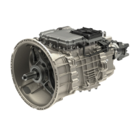
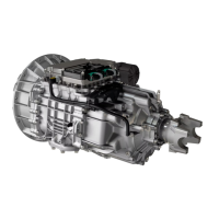
Mechatronic Transmission Module (MTM) Installation | Installation TRSM0950
Procedure – Installation
1. Place the transmission in a horizontal position.
NOTICE: The transmission must be in a horizontal
position prior to the MTM Installation procedure. Fail
-
ure to do so causes the sliding clutches to move out of
neutral and not align to the shift yokes. If the shift
yokes are not aligned to the sliding clutches, position
sensor fault codes set Active and the transmission will
not shift out of neutral.
2. Clean the sealing surfaces on the transmission and
Mechatronic Transmission Module (MTM) with Gasket
Remover.
NOTICE: Do not use abrasive scrapers or powered
tools to clean sealing surfaces or sealing surfaces may
be damaged and leak.
3. Inspect threaded bolt holes for debris and clean if nec-
essary.
NOTICE: Ensure there is nothing in the threaded bolt
holes or the transmission may be damaged when cap
screws are tightened.
4. Install the Rail B Engagement Tool (RR1088TR) to the
Main Housing and hand tighten with 2 MTM cap
screws.
5. Shift the Rail B Synchronizer to neutral.
6. Remove the Rail B Engagement Tool.
7. Move Rail C and Rail D sliding clutches to neutral.
NOTICE: The transmission must be in a horizontal
position prior to the MTM Installation procedure. Fail
-
ure to do so causes the sliding clutches to move out of
neutral and not align to the shift yokes. If the shift
yokes are not aligned to the sliding clutches, position
sensor fault codes set Active and the transmission will
not shift out of neutral.
 Loading...