Operation Overview
Eaton ePDU G3 Operation Manual P-164000277—Rev 1 www.eaton.com/ePDU 33
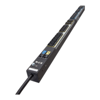
Figure 30. Communication and Serial Ports
Table 4. Communication and Environmental Monitoring Ports
Diagram
Reference Number Description
1 Serial or Environmental Monitoring (EMP) Port
2 Yellow Serial/EMP Port LED: RS-232 O
peration and Activity Status
OFF: No EMP connected
FLASHING: EMP connected
3 Green Serial/EMP Port LED: ePDU
Communication Status
OFF: ePDU start-up in progress
FLASHING: eNMC module operational
4 Ethernet 10/100 Base-T Port
5 Green Ethernet Port LED: Operation Transfer Rate Status
OFF: Port
operating at 10 Mbits/s
ON: Port operating at 100 Mbits/s
6 Yellow Ethernet Port LED: Connection a
nd Transmission Activity Status
OFF: ePDU not connected to the network
ON: ePDU connected to the network, but no activity
FLASHING: Port is sending or receiving (transmission active)
7 Reset Button
NOTETo restart the eNMC, insert a probe and press the button for 3 seconds (or until the LCD goes blank).
This does not reset power to the outlets.
8 USB Port: Used for firmware upgrade and configuration file download/upload
9 Daisy Chain Port
10 Yellow Daisy Chain Port LED: Transmission Activity S
tatus
FLASHING: ePDU is transmitting data
11 Green Daisy Chain Port LED: Role A
ssignment in Communication Protocol
ON: Device
FLASHING: Host

 Loading...


