INTERNAL BYPASS SWITCH INSTALLATION
Eaton FERRUPS FE/QFE UPS (500 VA–18 kVA) Installation Guide S 164201403 Rev B
www.eaton.com/powerquality
49
NOTE 9 UPS output circuits shall be installed in dedicated conduit
systems and not shared with other electrical circuits.
NOTE 10 The load fuse or circuit breaker should be sized to match the
load current requirements.
NOTE 11 For 208 Vac, use a step-up transformer For 480 Vac, use a
step-down transformer. Use an isolation transformer with a 120/240
grounded center-tapped neutral output. Do not use a buck/boost
transformer.
60 Hz 120 Vac Input - 120 Vac Output
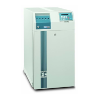
Figure 17. FE 4.3–7 kVA UPS with Internal Bypass Switch
Table 23. Minimum Recommended Circuit Breakers for 120 Vac
Charger 4.3 kVA 5.3 kVA 7 kVA
Standard 40 50 70
10A 45 60 70
20A 50 60 70
 Loading...