Installation i-on30EX/EXD
Page 20
connections are different on the expander
compared to the control unit.
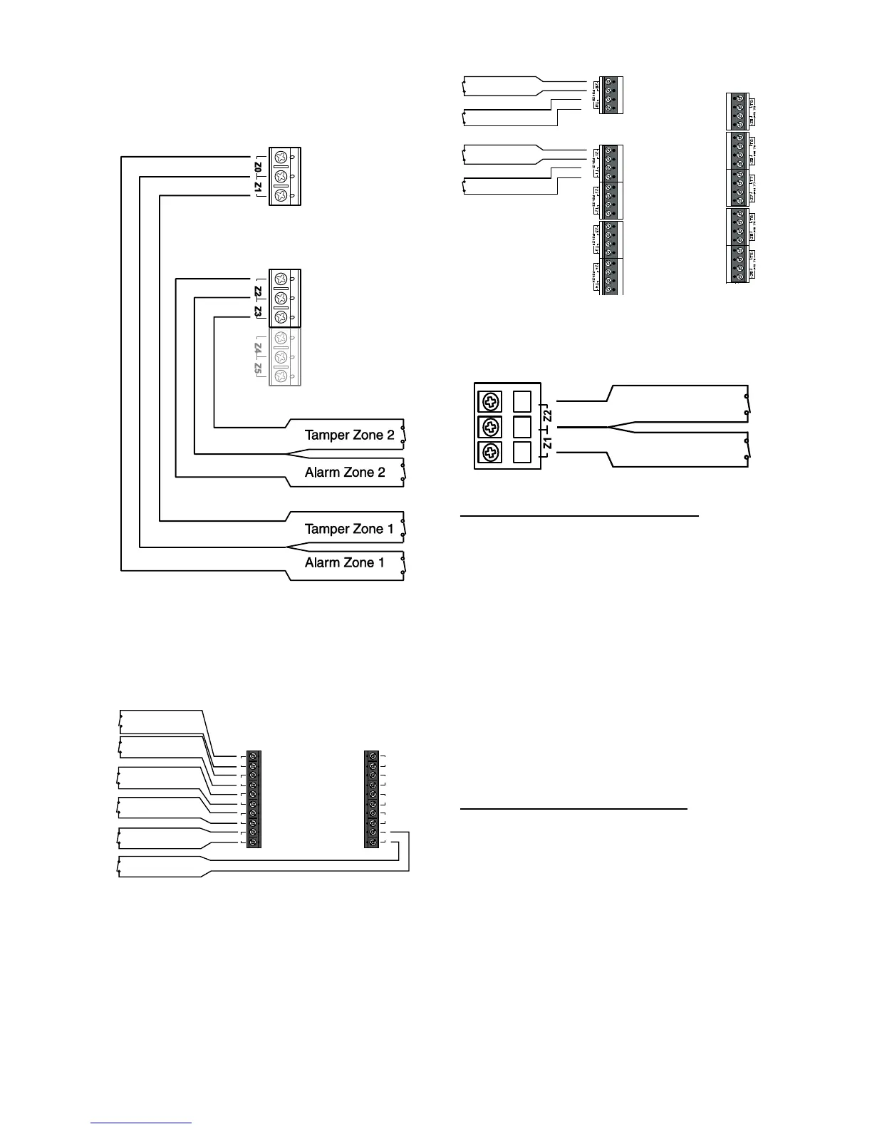
Figure 31 shows wiring for four-wire CCL zones
on the KEY-KPZ01.
Figure
Control Unit CCL Zone Wiring
Figure 29 shows the wiring for four-wire CCL
zones on the wired expander. Note that the
connections are different on the expander
compared to the control unit. Also note that zones
0, 6,7,8 and 9 are not available on the control unit,
and zones 5-9 are not available on the expander.
Figure
Wired Expander CCL Zone Wiring
Figure 30 shows the wiring for CCL zones on the
EXP-WCC wired expander. Note that the EXP-
WCC provides connectors for a total of ten
separate 4-wire CCL detectors, and that there are
separate terminals for both alarm and tamper.
Figure
KEY-KPZ01 CCL Zone Wiring
Two-Wire Closed Circuit Connections
With version 4.02 and higher software you can
connect two-wire CCL detectors to each pair of
zone terminals. To specify the zone wiring type
use the Installer Menu – System Options – Wire Zone
Type option and select “2-wire CC”.
On the control unit, EXP-W10 and EXP-WCC, if
required you can use one pair of zone terminals
as a common tamper, provided you program that
zone with the type “Tamper” from the Installer
Menu.
The EXP-WCC does not specifically have a 2-wire
CC zone type. However you can mimic the setting
by using “4k7/2k2/4-wire CC” zone wiring option,
and then connecting the detector to the alarm
terminals and placing a short across the tamper
terminals.
Fully Supervised Loop Connections
Figure 32 shows the wiring connections for FSL
zones on the control unit. Note that the resistance
values shown are examples.

 Loading...


