INM MTL 130-0126 Rev 13
11
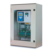
K1550 model mounted in a hazardous area
Connections to this display/control unit are provided on DIN-rail mounted terminals to the left of
the display. Terminal identities are provided on a label below them - see Figure 8.
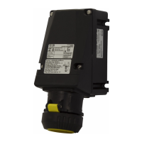
M20 threaded holes are provided in the bottom of the flameproof enclosure for these
connections - see Figure 3. They must be fitted with appropriately certified cable glands or
similarly approved blanking plugs for any unused ones.
Only one cable can be passed through a cable gland, so four holes are provided to accommodate
the following:
• AC power
• 4/20mA analogue output signal
• Alarm 1 - Fault alarm (as terminals 1 - 3 in Fig. 8)
• Alarm 2 - Range alarm (as terminals 4 - 6 in Fig. 8)
Figure 8 - Power and ouput terminals
17
18
16
4
3
2
1
6
5
20
19
Live
Neutral
Earth
C
Alarm 1 NC
Alarm 2 NO
Alarm 2 C
+
4/20mA –

 Loading...