11
05/08 AWB2528-1611en
2 Installation
The MFD-CP4-CO must only be installed and connected up
by trained electricians or a person familiar with the installa-
tion of electrical equipment. The MFD-CP4-CO is installed in
the following order:
• Mounting,
• Connecting the serial interface,
• Connecting the power supply.
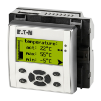
Mounting Install the display/operator unit in the front of a control
cabinet, a service distribution board, operator panel or in an
enclosure. You can protect the display/operator unit with a
protective membrane or cover, depending on the environ-
ment in which it is to be used. This must be fitted before the
MFD-CP4-CO is mounted and is therefore described in the
next section.
The MFD-CP4-CO communication module must be mounted
in such a way that all the terminals are protected against
direct contact, liquids and dust during operation.
For sufficient heat circulation around the device, the rear of
the MFD-CP4-CO and the terminals must have a clearance of
at least 3 cm from the wall or adjacent devices.
Figure 6: Minimum clearance for mounting
30
30
30
 Loading...