2
INM9491 Rev 3
Each 9491-PS can power a single 946x-ET Ethernet module.
It is not permitted to connect to both ia and ib outputs on the same 9491-PS module.
If multiple outputs are required for several Ethernet modules, there is a power distribution backplane
available to simplify the 24VDC input connection to the modules, or alternatively a number of them
can be DIN-rail mounted with a convenient “Powerbus” input.
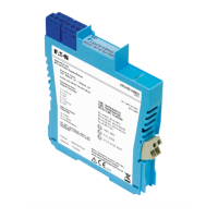
The 9491-PS module has LED power indication for both input and output (see Figure 2.3) along
with internal current limiting and electronic auto-reset circuit breaker action to protect the module in
the event of its output being short circuited or overloaded. This also minimises the power dissipation
during the fault to a negligible level, thus improving reliability.
Hazardous area
Safe
are
a
Figure 2.1
Zone 0
Ex ia IIB
application
Hazardous area
Safe
are
a
Figure 2.2
Zone 1
Ex ib IIB
application
Figure 2.3
9491-PS
top label and
LED indicators
Terminal Function
1 Ex ia IIB Groups C,D output +ve
2 n.c.
3 Ex ia IIB Groups C,D output –ve
4 n.c.
5 Ex ib IIB Output +ve
6 Ex ib IIB Output –ve
13 Supply –ve (Vs–)
14 Supply +ve (Vs+)
Zone 0
Zone 1
Terminal Function
1 Ex ia IIB Groups C,D output +ve
2 n.c.
3 Ex ia IIB Groups C,D output –ve
4 n.c.
5 Ex ib IIB Output +ve
6 Ex ib IIB Output –ve
7, 8 & 9 Supply –ve (Vs–)
10, 11 & 12 Supply +ve (Vs+)
Table 2.1
DIN-rail
mounting
connections
Table 2.2
Backplane
mounting
connnections
 Loading...