DMI
20
11/04 MN01219002Z-EN
Connection terminals
Tools
• Slot-headed screwdriver, slot width 3.5 mm, tightening
torque 0.6 Nm.
Cable connection cross-sections
• Solid: 0.2 to 4 mm
2
• Flexible with ferrule: 0.2 to 2.5 mm
2
Installation regulations, EMC
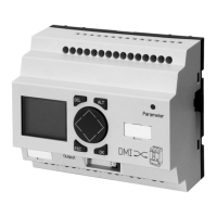
Observe the following requirements when installing a DMI in
a device or system:
• Always mount the DMI on an earthed top-hat rail.
• The clearance between the DMI and the circuit-breaker, as
well as between the DMI and the main conductors must
be at least 0.5 m.
• All cables and conductors connected to the DMI must not
be laid parallel to the main conductors. Conductors may
only be crossed on the shortest possible route and with a
minimum clearance of 10 cm.
• The minimum bending radius of the communication cable
between NZM and DMI is 130 mm.
• Fit the supplied ferrite ring on the cable (NZM-XDMI-CAB)
to the circuit-breaker approximately 5 to 10 cm from the
plug at the circuit-breaker end.
h
These measures must be observed in order to ensure the
EMC characteristics specified in a section
“Electromagnetic compatibility (EMC)”, Page 70.
Artisan Technology Group - Quality Instrumentation ... Guaranteed | (888) 88-SOURCE | www.artisantg.com

 Loading...


