4 Operational
4.4 Commissioning with local controls
DC1…20… and DC1…OE1 Variable Frequency Drives 02/20 MN040059EN www.eaton.com 127
Example
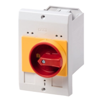
Table 21: Selector switch for DC1-…A6S…
Switch position
Parameter Description
P-12 P-15
REV STOP FWD 0 0 Factory Default Configuration
Run Forward or Reverse with speed controlled from
the local POT
STOP STOP FWD 0 5, 7 Run forward with speed controlled form the local
POT
Run Reverse – Disabled
Preset Speed 1 STOP FWD 0 1 Run Forward with speed controlled from the local
POT
Preset Speed 1 provides a ‘Jog’ Speed set in P-20
REV STOP FWD 0 6, 8 Run Forward or Reverse with speed controlled from
the local POT
Run in Auto STOP Run in Hand
0 4 Run in Hand – Speed controlled from the local POT
Run in Auto – Speed controlled using Analog input 2
e.g. from PLC with 4-20mA signal.
Run in Speed Control STOP Run in PI Control 5 1 In Speed Control the speed is controlled from the
local POT
In PI Control, Local POT controls PI set point.
Run in Preset Speed
Control
STOP Run in PI Control
5 0, 2, 4, 5,
8, 9, 10,
11, 12
In Preset Speed Control, P-20 sets the Preset Speed
In PI Control, POT can control the PI set point
(P-44 = 1).
Run in Hand STOP Run in Auto 3 6 Hand – Speed controlled from the local POT
Auto – Speed Reference from Modbus
Run in Hand STOP Run in Auto
3 3 Hand – Speed reference from Preset Speed 1 (P-20)
Auto – Speed Reference from Modbus
FWD = Forward Run
REV = Reverse Run
REV FWD
0
REV FWD
0

 Loading...
