32
Chapter 6—Installation requirements
POWERXL SERIES VFD MN040002EN—February 2018 www.eaton.com
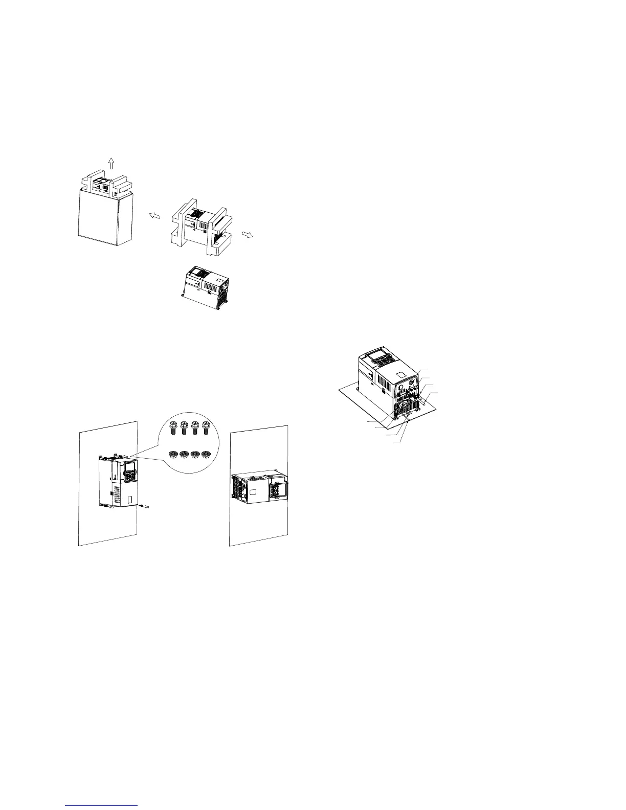
Standard drive mounting
FR0 mounting instructions
Step 1: Lift the drive out from the carton, remove the
packaging.
Step 2: Attach the drive to the mounting plate with four
M5x15 screws and four M5 nuts. The opening
dimension on the mounting plate should follow
required dimension (refer to the drive mounting
template printed on the outside carton. The drive
can be mounted vertically or horizontally according
to customer’s needs.
Screw: 4-M5*15
Nut: 4-M5
Vertical Mounting Horizontal Mounting
Step 3:
1. EN version FR0 or U.S. version FR0 with EMC kit.
a. Input wiring: Run the L1, L2, L3 wires through a
magnetic ring and wind one lap, fix the L1, L2,
L3 wires and magnetic ring with a cable tie, then
connect the L1, L2, L3 wires to input terminals.
Connect the input grounding wire to the bottom
metal plate with an M4x10 screw.
b. Output wiring: Attach an L-shape EMC grounding
plate to the bottom of drive with two M4x8 flat
screws. Connect the output U, V, W wires to output
terminals. Connect the output grounding wire to the
bottom metal plate with an M4x10 screw. Clamp the
output cable shield to the L-shape EMC grounding
plate with a small rectangular EMC grounding plate
and two M4x15 screws.
2. U.S. version FR0 without EMC kit, there are no
magneticring and EMC grounding plates, but it is
necessary to connect the output cable shield to the
bottom metal surface with an M4x10 screw.
Output cable
Screw: 2-M4*15
Screw: 2-M4*8 at
Screw: 2-M4*10
Input grounding wire
Input power wires
Cable tie
Magnetic ring

 Loading...


