Installation Leaet IL03901007E
Effective June 2011
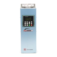
S611 User Interface Remote Mounting
Installation Leaflet
Disconnect power in accordance with federal, state, and local codes and remove the S611 from the enclo-
sure or mounting panel.
NOTE: Servicing the S611 while installed in an enclosure or mounted vertically on a panel is not recom-
mended.
Place the unit on a clean work surface.
Cover Removal
1. Disconnect all control wiring and tie wraps securing any wiring to the cover assembly.
2. Remove cover screws with nuts. 6 each on Frames A – D, 4 each on Frames E - F.
NOTE: Cover screw nuts are prevented from rotating but are not retained in place by the pole
supports. Do not allow hardware to fall into the soft starter.
3. Lift top of cover approximately 6” to gain access to the BYPASS VOLTAGE contactor
connector mounted on the Printed Circuit Board (PCB). See Figure 1.
4. Press locking tab on BYPASS VOLTAGE contactor connector and disconnect from the PCB.
5. Carefully rotate cover to rest onto work surface as shown. See Figure 2.
Figure 1 - Contactor Connector Figure 2 - Cover Position
Mounting The Remote Display
If necessary, remove the User Interface from the cover using a 30mm pilot device tool (E22CW recom-
mended).
1. Drill or punch two 30mm pilot holes on 1.75-inch centers a minimum of 1.60 inches (40.6 mm)
from every door gasket (see Figure 3).
2. Insert remote display through the door and add two gaskets provided behind the door
(see Figure 4).