Installation Leaet IL03901007E
Effective June 2011
S611 Soft Starters
Eaton Corporation
Electrical Sector
1111 Superior Ave.
Cleveland, OH 44114
United States
877-ETN-CARE (877-386-2273)
Eaton.com
© 2008 Eaton Corporation
All Rights Reserved
Publication No. IL03901007E
June 2011 Rev.001
PowerChain Management is a registered
trademark of Eaton Corporation.
All other trademarks are property of their
respective owners.
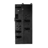
Figure 3 - Pilot Device Holes - Inch[mm]
Minimum to all
gaskets or door
mounted devices
1.60
[40.6]
1.75
[44.5]
Gaskets
E22CW
Tighten
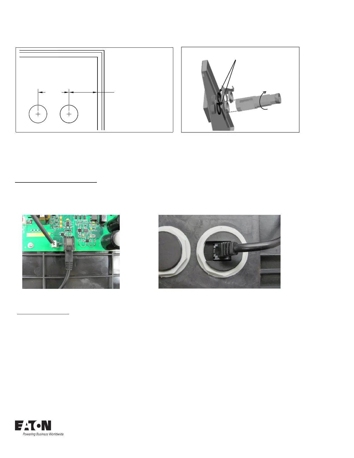
Figure 4 - Door Cut Away For Clarity
3. Orient strain relief bracket with respect to your chosen cable routing.
4. Add two jam nuts provided and tighten 30mm pilot device tool until the strain relief bracket is
flush with the enclosure door, tighten an additional ½ of a turn.
Connecting the Remote Display
1. Route cable from User Interface to PCB (see Figures 5 & 6).
2. Secure cable to the strain relief bracket using any suitable tie wrap.
3. Reinstall cover assembly.
Figure 5 - Interconnecting Cable - PCB Figure 6 - Interconnecting Cable - User Interface
Cover Reinstallation
1. As the cover is placed onto the supports, carefully guide wiring into place.
2. Ensure that the BYPASS VOLTAGE contactor connector is properly connected prior to installing
the cover screws.
3. Install and torque all cover assembly screws to 22 – 27 lb-in.
4. Reinstall control wiring.

 Loading...