3
Instruction Leaet IL01301015E
Effective November 2016
Installation instructions for Series NRX
Type NF frame xed breaker rear connect,
front connect, and hybrid congurations
EATON www.eaton.com
Rear connected congurations
m CAUTION
DO NOT EXCEED THE RECOMMENDED TORQUE VALUES WHEN MAKING
BOLTED CONNECTIONS TO THE EQUIPMENT OR TO THE ADAPTERS
THEMSELVES, ALL WHICH HAVE PRE-TAPPED HOLES. IN ADDITION,
ANY CONNECTION HARDWARE USED SHOULD BE THE EXACT LENGTH
REQUIRED AND SHOULD NOT EXTEND OUT PAST THE MOUNTING
HOLE. FAILURE TO FOLLOW THESE REQUIREMENTS COULD RESULT IN
EQUIPMENT DAMAGE AND/OR FAILURE.
m IMPORTANT
IT IS RECOMMENDED THAT APPROPRIATE INTERPHASE BARRIERS BE
INSTALLED BETWEEN INSIDE AND OUTSIDE PRIMARY TERMINALS WITH
ALL REAR CONNECTED CONFIGURATIONS TO ENSURE INSULATION
INTEGRITY. IF INTERPHASE BARRIERS ARE ORDERED FROM EATON,
INSTALLATION INSTRUCTIONS ARE PROVIDED WITH THE BARRIERS.
Rear connect kit installation
This breaker configuration uses universal bus adapters that bolt to
the rear primary terminal pads (Figure 3). This type of adapter only
supports bus connections.
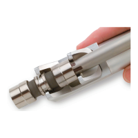
ØD
L
W
Dimensions in inches (mm)
L = 2.36 (59.9)
W = 1.96 (49.8)
D = 0.53 (13.5)
Figure 3. Universal bus adapter
For a horizontal bus connection, bolt a universal bus adapter
to the vertically positioned mounting holes of a rear primary
terminal pad using the hardware provided (Figure 4). For a vertical
bus connection, bolt a universal bus adapter to the horizontally
positioned mounting holes using the hardware provided.
Complete the other adapter connections in a similar fashion. The line
and load adapters can be mounted in opposite orientations at the
line and load sides (Figure 5). Torque the bolted connections to
10 ft-lb (13.6 N∙m).
To remove the adapters, reverse the procedure described above.
Figure 4. Horizontal universal bus connection
Horizontal
orientation
Vertical
orientation
Figure 5. Universal bus adapters in opposite orientations
 Loading...