5
Instruction Leaet IL01301015E
Effective November 2016
Installation instructions for Series NRX
Type NF frame xed breaker rear connect,
front connect, and hybrid congurations
EATON www.eaton.com
Front connected congurations
m CAUTION
IT IS IMPORTANT NOT TO EXCEED THE RECOMMENDED TORQUE VALUES
WHEN MAKING BOLTED CONNECTIONS TO THE EQUIPMENT OR TO THE
ADAPTERS THEMSELVES, ALL WHICH HAVE PRE-TAPPED HOLES. FAILURE
TO FOLLOW THESE REQUIREMENTS COULD RESULT IN EQUIPMENT
DAMAGE AND/OR FAILURE.
This breaker configuration has bus adapters that are internal to the
breaker and are intended to accommodate cable terminals and other
external bus connections. These cannot be replaced in the field.
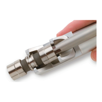
The arc hood on the line side and the shroud on the load side serve
to insulate the bus adapters from their surroundings (Figure 8).
Refer to Table 2 for a list of available front connectors.
Arc hood
Shroud
Bus
adapters
Figure 8. Bus adapters at the line and load sides—back cover
not shown to highlight the bus adapters
Table 2. List of front connectors
List
number Connector
Catalog
number
UL 489 UL 1066 IEC
42/50 kA 65 kA 42/50 kA 65 kA 42/50 kA 65 kA
1 Bus conductor extension NRXBUSEXT
n
Future None None Future Future
2 Cable terminal (2 holes)
with control wire provision
TA700NB1M
TA700NB1MCWT
n n
None None
n n
3 Cable terminal (3 holes)
with control wire provision
TA1000NB1M
TA1000NB1MCWT
n n
None None
n n
4 Cable terminal (4 holes)
with control wire provision
TA1200NB1M
TA1200NB1MCWT
Future Future None None Future Future
Table 3. Cable terminal specifications
Maximum
breaker amperes
Terminal
body material Wire type
AWG wire range /
number of conductors
Metric wire
range mm
2
Catalog
number
Standard Cu/Al pressure terminals
700 Aluminum Cu/Al 1–500 kcmil (2) 50–240 TA700NB1M
TA700NB1MCWT
1000 Aluminum Cu/Al 3/0–400 kcmil (3) 95–185 TA1000NB1M
TA1000NB1MCWT
1200 Aluminum Cu/Al 4/0–500 kcmil (4) 120–240 TA1200NB1M
TA1200NB1MCWT
 Loading...