SLX9000 Adjustable Frequency Drives User Manual
8-16 For more information visit: www.eaton.com
MN04003020E
January 2009
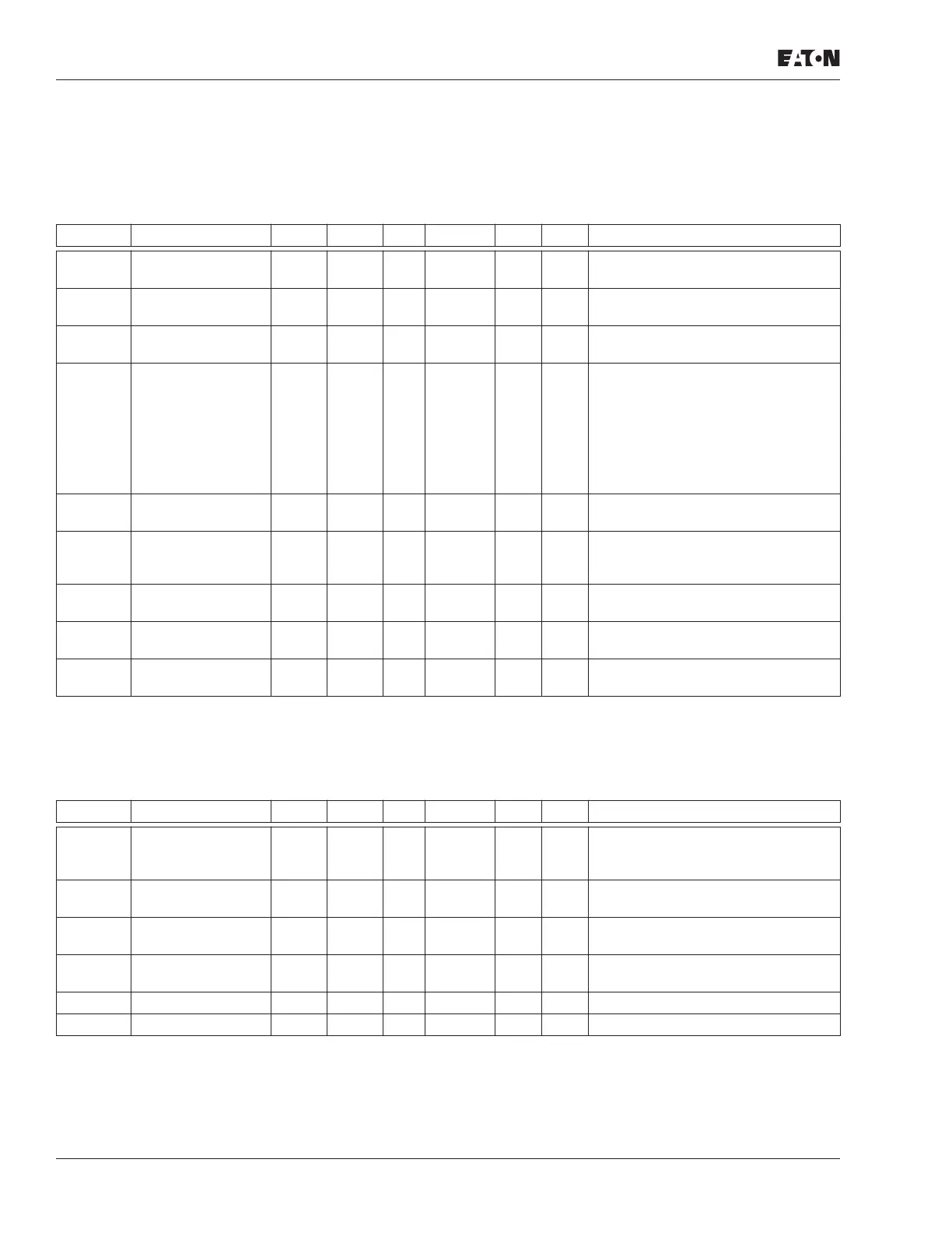
Pump and Fan Control Parameters (Control Keypad: Menu P2 ➔ P2.10)
Note: Group P2.10 is visible only if the value of par 2.9.1 is set to 2.
Table 8-14: Pump and Fan Control Parameters, P2.10
Keypad Control (Control Keypad: Menu K3)
The parameters for the selection of control place and direction on the keypad are listed in
Table 8-15. See the Keypad Control Menu on Page 5-10.
Table 8-15: Keypad Control Parameters, K3
Code Parameter Min. Max. Unit Default Cust ID Note
P2.10.1 Number of auxiliary
drives
0 3 1 1001
P2.10.2 Start delay,
auxiliary drives
0.0 300.0 s 4.0 1010
P2.10.3 Stop delay,
auxiliary drives
0.0 300.0 s 2.0 1011
P2.10.4 Autochange 0 4 0 1027 0 = Not used
1 = Autochange with aux pumps
2 = Autochange with drive & aux
pumps
3 = Autochange and interlocks (aux
pumps)
4 = Autochange and interlocks (drive
& aux pumps)
P2.10.5 Autochange
interval
0.0 3000.0 h 48.0 1029 0.0 = TEST = 40 s
Elapsed time for autochange
P2.10.6 Autochange;
Maximum number
of auxiliary drives
0 3 1 1030 Autochange level for auxiliary drives
P2.10.7 Autochange
frequency limit
0.00 par.
2.1.2
Hz 25.00 1031 Autochange frequency level for
variable speed drive
P2.10.8 Start frequency,
auxiliary drive 1
Par.
2.10.9
320.00 Hz 51.00 1002
P2.10.9 Stop frequency,
auxiliary drive 1
Par.
2.1.1
Par.
2.10.8
Hz 10.00 1003
Code Parameter Min. Max. Unit Default Cust ID Note
P3.1 Control place 1 3 1 125 1 = I/O terminal
2 = Keypad
3 = Fieldbus
R3.2 Keypad reference Par.
2.1.1
Par.
2.1.2
Hz
P3.3 Direction (on
keypad)
0 1 0 123 0 = Forward
1 = Reverse
R3.4 Stop button 0 1 1 114 0 = Limited function of Stop button
1 = Stop button always enabled
R3.5 PID reference 0.00 100.00 % 0.00
R3.6 PID reference 2 0.00 100.00 % 0.00 Selected with digital inputs

 Loading...


