SLX9000 Adjustable Frequency Drives User Manual
MN04003020E
For more information visit: www.eaton.com 9-7
January 2009
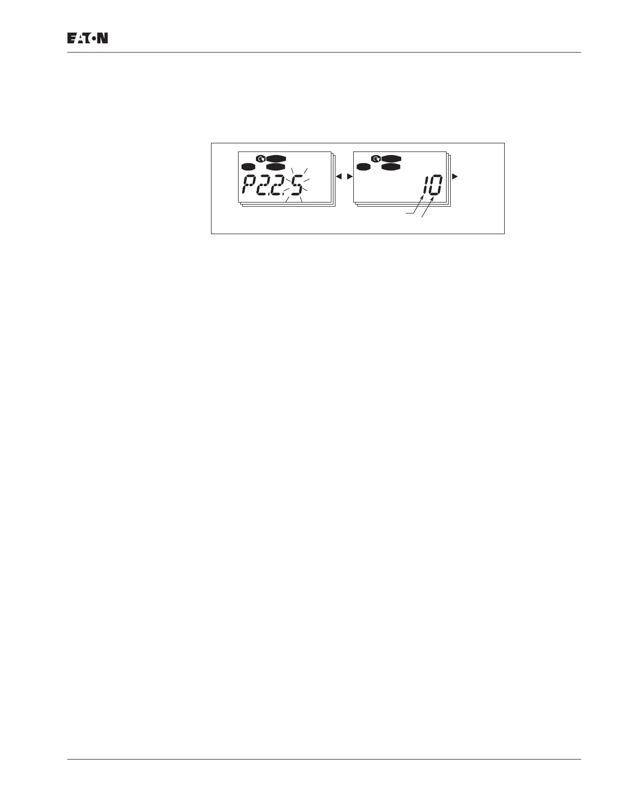
Figure 9-2: AI1 Signal Selection
2.2.5 AI1 signal selection ID377
Connect the AI1 signal to the analog input of your choice with this parameter.
The value of this parameter is built from the board indicator and the respective input
terminal number. See Figure 9-2 above.
Board indicator 1 = Local inputs
Board indicator 2 = Expander board inputs
Input number 0 = Input 1
Input number 1 = Input 2
Input number 2 = Input 3
—
—
Input number 9 = Input 10
Example:
If you set the value of this parameter to 10, you have selected the local input 1 for the
AI1 signal. Again, if the value is set to 21, the expander board input 2 has been
selected for the AI1 signal.
If you want to use the values of analog input signal for testing purposes only, you
can set the parameter value to 0 – 9. In this case, value 0 corresponds to 0%, value 1
corresponds to 20% and any value between 2 and 9 corresponds to 100%.
STOP
READY
I/O Term
STOP
READY
I/O Term
Change
Value
Location Indicator
Input Number

 Loading...


