SLX9000 Adjustable Frequency Drives User Manual
8-4 For more information visit: www.eaton.com
MN04003020E
January 2009
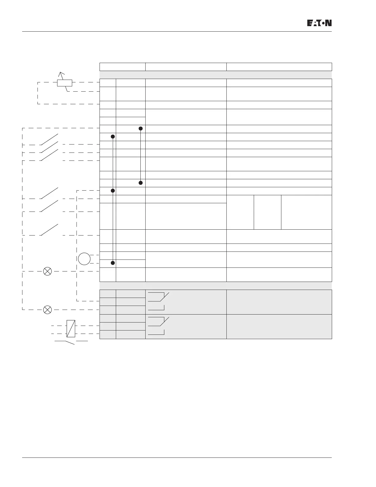
Table 8-3: Default I/O Configuration, All 230V, FR7 – FR8 460V and All 575V
Terminal Signal Description
OPTA1
1 +10V
ref
Reference output Voltage for potentiometer, etc.
2 AI1+ Analog input, voltage range
0 – 10V DC
Voltage input frequency reference
3 AI1- I/O Ground Ground for reference and controls
4 AI2+ Analog input, current range
0 – 20 mA
Current input frequency reference
5 AI2-
6 +24V Control voltage output Voltage for switches. etc. max 0.1A
7 GND I/O ground Ground for reference and controls
8 DIN1 Start forward Contact closed = start forward
9 DIN2 Start reverse Contact closed = start reverse
10 DIN3 External fault input
(programmable)
Contact open = no fault
Contact closed = fault
11 CMA Common for DIN1 – DIN3 Connect to GND or +24V
12 +24V Control voltage output Voltage for switches (see #6)
13 GND I/O ground Ground for reference and controls
14 DIN4 Multi-step speed select 1 DIN4 DIN5 Frequency ref.
15 DIN5 Multi-step speed select 2 Open
Closed
Open
Closed
Open
Open
Closed
Closed
Ref.U
in
Multi-step ref.1
Multi-step ref.2
RefMax
16 DIN6 Fault reset Contact open = no action
Contact closed = fault reset
17 CMB Common for DIN4 – DIN6 Connect to GND or +24V
18 AO1+ Output frequency
Analog output
Programmable
Range 0 – 20 mA/R
L
, max. 500Ω
19 AO1-
20 DO1 Digital output
READY
Programmable
Open collector, I ≤ 50 mA, U ≤ 48V DC
OPTA2
21 RO1 Relay output 1
RUN
22 RO1
23 RO1
24 RO2 Relay output 2
FAULT
25 RO2
26 RO2
mA
READY
RUN
Reference potentiometer
1 – 10 kΩ
220V
AC

 Loading...


