Do you have a question about the Eaton SVS/12 and is the answer not in the manual?
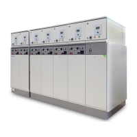
Overview of the SVS/12 system, its modular construction, design, and operation features.
Guidance on the target audience and the structure of the user manual.
Details applicable regulations, safety measures, warning symbols, and general safety instructions.
Covers technical specifications, radiation/noise emission, heating elements, and diagram references.
Describes panel types for 630 A (420 mm wide) and 1250 A (630 mm wide) systems.
Details circuit-breaker, load-break switch, fuse panels, busbar, bus-section, and metering panels.
Details circuit-breaker, busbar connection, bus-section, and metering panels for 1250 A.
Explains interlocks for 630 A and 1250 A panels and general safety protocols.
Provides electrical data and dimensions/weights for 630 A and 1250 A panels.
Covers general guidelines, clear space, escape routes, entrances, and climate requirements.
Details transport methods, instructions, accessories, and setting up the installation.
Overview of various cable connection methods for 630 A panels.
Details connection of plastic-insulated cables using plugs to 12-24 kV panels.
Connects plastic-insulated cables up to 50 mm² to 12-24 kV switch/fuse panels.
Connects plastic-insulated cables up to 120 mm² with straight plugs to 12-24 kV panels.
Connects paper-insulated lead-covered cables up to 70 mm² using grease-filled boxes.
Connects paper-insulated lead-covered cables up to 150 mm² using grease-filled boxes.
Connects paper-insulated lead-covered cables up to 240 mm² with soldering gland.
Connects paper-insulated lead-covered cables up to 240 mm² with plastic entry bushing.
Procedure for filling cable boxes with grease using a filling device.
Connects plastic-insulated cables up to 70 mm² using dry cable boxes.
Connects plastic-insulated cables from 95 mm² to 240 mm² using dry cable boxes.
Instructions for assembling a capacitive sensor for voltage indicators.
Overview of various cable connection methods for 1250 A panels.
Details connection of plastic-insulated cables using plugs to 1250 A panels.
Connects plastic-insulated cables up to 630 mm² via cable socket connection.
Defines required training, operating conditions, PPE, and dangers for bystanders.
Details control panels for 630 A and 1250 A panels, including indicators and controls.
Provides steps for mechanical and electrical switching on/off for 630 A panels.
Provides steps for mechanical and electrical switching on/off for 1250 A panels.
Describes mechanical and electrical operation of the disconnector for 630 A panels.
Describes mechanical and electrical operation of the disconnector for 1250 A panels.
Explains voltage indicators and phase comparison procedures for 630 A and 1250 A panels.
Details how to use padlock interlocks for preventing operations on various panels.
Describes overcurrent and short-circuit current indicators for 630 A panels.
Installation and disconnection procedures for cable side voltage transformers on 630 A panels.
Procedure for opening and closing the 600 mm high instrument compartment.
Covers various methods for earthing cables, including via switches and back-up earth systems.
Step-by-step guide for replacing high-voltage fuses in 630 A panels.
Procedures for testing cables via terminal blocks and right-angle plugs.
Covers preparation, visual inspection, panel checks, and function testing for commissioning.
Details dismantling procedures for the switchgear.
Guidelines for environmentally responsible disposal of the switchgear.
Specifies maintenance intervals and procedures for 630 A and 1250 A panels.
Guides on checking and maintaining the mechanism, including lubrication points.
Procedure for topping up grease levels in cable boxes for 630 A panels.
Instructions for cleaning the switchgear installation if it becomes dirty.
Procedure for changing bottom contacts in 24 kV fuse holders for 630 A panels.
Contact information for Eaton Electrical Services & Systems for troubleshooting and repairs.
Lists and illustrates available accessories such as operating handles and keys.
Defines terms related to personnel safety, competence, and responsibilities in electrical operations.
Details the components of the information pack supplied with the equipment.
Instructions for use, design, technical data, and connection of the Wega 1.2 voltage detector.
Information on the Orion 3.0 phase monitor, including technical data and operating modes.
| Brand | Eaton |
|---|---|
| Model | SVS/12 |
| Category | Control Systems |
| Language | English |