Page 2 of 3
5. Testthealarmforproperoperation.Ifalarmdoesnotsound,reviewStep4.Afterconrmingproperoperation,axtheprovidedWarningLabeltothe
dashboard of the vehicle in plain view of the operator. Do not operate this vehicle if the back-up alarm is not functioning properly.
6. Add requirement to “test back-up alarm system before operating vehicle” to the daily maintenance log and notify your supervisor or team leader that
peopleoperatingthisvehicleMUSTconrmproperalarmoperationatthebeginningofeachworkshift.Do not operate this vehicle if the back-up
alarm is not functioning properly.
As the operator of a vehicle, you should always know when the alarm is sounding and when it is not sounding. Should the alarm become inoperative, dis-
continue vehicle operation and notify your supervisor or team leader. Operating a vehicle with an alarm that is not functioning properly could endanger the
lives and/or property of those who depend on the alarm signal for safety.
Back-up alarm testing must be itemized on the daily maintenance log. An alarm on an operating vehicle must be tested prior to the vehicle’s use at the
beginningofeachworkshift.Checkthedailymaintenancelogtoconrmacceptableresultsofthistestingbeforeoperatingthevehicle/mobileequipment.
- More frequent testing may be necessary if the vehicle is operating in adverse conditions.
-Groundguidanceshouldbeprovidedtothedriverwhenbackingavehicleinajobenvironmentwheretheaudibilityofthealarmisinquestion.
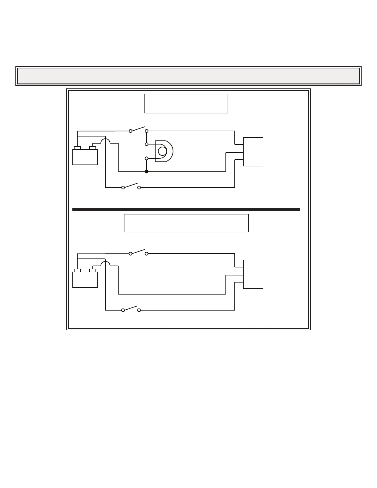
4. Thisunitrequiresareliablepowerandgroundconnectionforoperation.CompletethewiringaccordingtothewiringdiagraminFigure1.Use18gauge
wire (minimum) Figure 1A if vehicle back-up light circuit is used, or Figure 1B if a user installed switch is required, and observe correct polarity. WARN-
ING!! Anytime the back-up alarm is in operation, continuity must be maintained between the positive voltage of the power source and the positive termi-
nal of the back-up alarm as well as between the negative terminal of the back-up alarm and the common ground (the vehicle member to which all wire
groundsareconnected).Duringoperationthevoltagedierentialbetweenthepositivevoltageofthepowersourceandthepositiveterminal(+)ofthe
back-upalarmshallnotexceed150mV.Duringoperationthevoltagedierentialbetweenthecommongroundandthenegativeterminal(-)ofthealarm
shall not exceed 150mV. Route wire in a protected manner in accordance with vehicle manufacturer recommendations. NOTE: The back-up alarm will
not operate when its power connections are reversed and is protected against reversed polarity up to 400V.
Alistingofproductspecicationsisavailableuponrequest.
IMPORTANT! DO NOT spray any coating material, e.g. paint, undercoating, etc., over the sound opening. DO NOT install the alarm or its wiring
in proximity to ignition wires. Failure to observe these conditions may have an adverse eect on the alarm’s performance.
+ -
+ POSITIVE - ALARM
- NEGATIVE
+ POSITIVE - WARBLE
BACK-UP ALARM SWITCH
BACK-UP ALARM
BACK-UP LIGHT
SWITCH FOR WARBLE
(USER INSTALLED)
BATTERY
BACK-UP LIGHT SWITCH
+ -
+ POSITIVE - ALARM
- NEGATIVE
+ POSITIVE - WARBLE
BACK-UP ALARM SWITCH
(USER INSTALLED)
BACK-UP ALARM
SWITCH FOR WARBLE
(USER INSTALLED)
BATTERY
USER INSTALLED REVERSE ACTIVATED SWITCH
BACK-UPLIGHTSWITCH
BACK-UPLIGHTSWITCH
BACK-UPLIGHT
BATTERY
SWITCHFORWARBLE
(USERINSTALLED)
BACK-UPALARM
+POSITIVE-ALARM
-NEGATIVE
+POSITIVE-WARBLE
USERINSTALLEDREVERSEACTIVATEDSWITCH
BACK-UPLIGHTSWITCH
(USERINSTALLED)
BATTERY
SWITCHFORWARBLE
(USERINSTALLED)
BACK-UPALARM
+POSITIVE-ALARM
-NEGATIVE
+POSITIVE-WARBLE
Specications
Vehicle Operations
 Loading...