Specications:
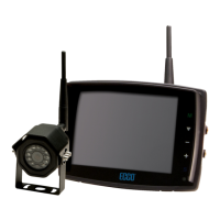
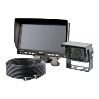
CAMERA C2013B
Image CMOS
Voltage Requirement 12V
Effective Pixels 725 x 488
Power Consumption 1W
Lens Size 1/4”
Lens Angle 120°
Audio No
Light Sensor Auto Switch B&W
Infrared LEDs 18
Pigtail Connection: CAM Male 4 Pin Threaded
Housing Aluminum Alloy
Mech. Vibration 8g
Mounting Rear/Front
Weight 0.58 lbs
Dimensions (WxHxD) 2.92”x3.01”x2.62”
Operating Temp. -4°F to 158°F
IP Rating IP69K
Approvals FCC,CE,RoHS
Current Consumption 175mA Max
MONITOR M7000B
Screen Size 7” (4:3) and (16:9)
Controller 2 Camera
Voltage 12-24 VDC
Power Approximate: 5W
Mirror Imaging Yes (via Camera and Monitor Switch)
Resolution 800(W)XRGBX480(H)
System PAL/NTSC
Viewing Angle L/R/U/D: 60º/60º/40º/60º
Visible Area 154X86mm
Contrast 400:1
Split Screen Feature No
AV Compatible Yes
DVR Compatible No
Audio No
Brightness 400cd/m2
Light Sensor Auto Dim
Camera Selection 1-2 Via Trigger Wires
Connection: CAM Female 4 Pin Threaded
Connection (Monitor Pigtail) Male 9 Pin
Connection: CB N/A
Housing Plastic
Mounting Pedestal
Mech. Vibration Pedestal Bracket - 3G
Weight 0.88 lbs
Dimensions (WxHxD) 6.85” x 4.49” x 0.94”
Operating Temp -4°F to 158°F
Remote Control Yes
Approvals FCC,CE,RoHS
Caution! When drilling into any vehicle surface, make sure that the area is free from any electrical wires, fuel lines,
vehicle upholstery, etc. that could be damaged.
Notes:
1. Larger wires and tight connections will provide longer service life for components. For high current wires it is recommended
that terminal blocks or soldered connections be used with shrink tubing to protect the connections. Do not use insulation
displacement connectors (e.g., 3M Scotchlock type connectors)
2. Route wiring using grommets and sealant when passing through compartment walls. Minimize the number of splices to
reduce voltage drop. High ambient temperatures (e.g., under-hood) will signicantly reduce the current carrying capacity of
wires, fuses, and circuit breakers. All wiring should conform to the minimum wire size and other recommendations of the
manufacturer and be protected from moving parts and hot surfaces. Looms, grommets, cable ties, and similar installation
hardware should be used to anchor and protect all wiring.
3. Fuses or circuit breakers should be located as close to the power takeoff points as possible and properly sized to protect the
wiring and devices.
4. Particular attention should be paid to the location and method of making electrical connections and splices to protect these
points from corrosion and loss of conductivity.
5. Ground termination should be only be made to substantial chassis components, preferably directly to the vehicle battery.
6. Circuit breakers are very sensitive to high temperatures and will “false trip” when mounted in hot enviroments or operated
close to their capacity.
 Loading...