Do you have a question about the Eci Telecom NPT-1020 and is the answer not in the manual?
Specifies the target audience for the NPT-1020 Installation, Operation, and Maintenance Manual.
Outlines the structure and content of the NPT-1020 Installation, Operation, and Maintenance Manual.
Explains the meaning of different types of notes, cautions, warnings, and laser/ESD warnings used in the guide.
Lists other ECI publications that may assist with installation and commissioning processes.
Provides contact details for obtaining technical documentation from ECI.
Details how to get technical assistance for network design and installation from ECI's specialized personnel.
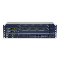
Describes the physical components and architecture of the NPT-1020 packet transport platform.
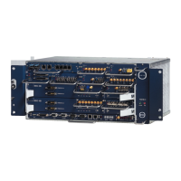
Details the EXT-2U expansion unit, its purpose, and components for enhancing NPT platforms.
Provides an overview of important information for a safe and trouble-free installation of NPT-1020 equipment.
Outlines the main steps involved in the installation sequence of NPT-1020 equipment.
Details the preliminary survey and considerations for preparing the installation site for NPT-1020 platforms.
Specifies the environmental conditions required for NPT-1020 equipment installation.
Provides guidelines for choosing the physical location for NPT-1020 platforms, considering dimensions and access.
Describes the DC and AC power supply requirements and configurations for NPT-1020 platforms.
Lists the standard technician tools and recommended equipment for NPT-1020 platform installation.
Provides instructions for cleaning optical connectors used with NPT-1020 equipment.
Provides guidelines and recommended practices for installing NPT-1020 platforms and ancillary equipment in racks.
Provides guidelines and recommended practices for installing NPT-1020 platforms and ancillary equipment in racks.
Describes the typical installation of a NPT-1020 shelf within an ECI ETSI rack, including ancillary equipment.
Guides on installing multiple NPT-1020 units and accessories efficiently within a single rack.
Provides information for preparing cables and optical fibers, including grounding, power, and timing cables.
Details the process and requirements for preparing grounding cables for NPT-1020 platform installation.
Explains the preparation of DC power cables, including RAP input and platform power cables.
Provides specific instructions for preparing RAP input power cables, including color coding and termination.
Details the installation of platform power cables connecting the RAP unit to the NPT-1020 power modules.
Describes the connection and length of alarm cables used between the NPT-1020 shelf and the RAP.
Explains how to connect management cables using RJ-45 connectors for out-of-band management.
Details the connection of timing cables to the NPT-1020's RJ-45 timing interfaces.
Describes the connection of TOD/1PPS timing cables for timing and synchronization signals.
Lists the types of electric traffic cables and mating connectors needed for NPT-1020 interfaces.
Provides guidance on preparing optical fibers, including cable types, connectors, and routing through the FST.
Covers general safety guidelines for working with NPT-1020 equipment, including grounding.
Emphasizes the importance of proper grounding for all equipment to ensure safety and system integrity.
Details the specific requirements for grounding racks, including connections to site grounding bars.
Outlines the DC power supply requirements, including voltage, circuit breakers, and disconnect devices.
Describes the AC/DC converter modules and recommended AC source circuit breakers for NPT-1020.
Covers the laser safety requirements, including classification and warnings for optical interfaces.
Explains the laser classification of the NPT-1020 equipment according to safety standards.
Identifies the warning labels affixed to the platform front panel indicating laser safety classification.
Provides statutory warnings regarding laser radiation awareness for installation and maintenance personnel.
Lists important precautions to observe when operating equipment with laser devices.
Provides technical information regarding optical modules and their laser specifications for the NPT-1020.
Provides guidelines for protecting NPT-1020 equipment and components from electrostatic discharge.
Emphasizes the need for personnel training in handling ESD-sensitive equipment and performing field work.
Details the requirements and toolkit for establishing a temporary ESD Protected Area (EPA) for safe handling.
Outlines essential arrangements and procedures for personnel working within a temporary EPA to ensure ESD protection.
Discusses ECI's commitment to environmental quality and product safety, including ISO standards and RoHS compliance.
Provides general instructions for installing the NPT-1020 and auxiliary equipment, referencing site plans.
Lists assumptions and preparatory steps required before starting equipment installation in racks.
Describes the correct order of execution for installing NPT-1020 system components and related equipment.
Details the process for unpacking equipment, performing visual inspections, and reporting any damage or missing parts.
Presents the recommended rack types and installation options for NPT-1020 platforms.
Covers the installation of ancillary units like RAP, FST, ODF, and xDDF-21 in racks.
Provides step-by-step instructions for installing the RAP-BG unit in a rack.
Guides on preparing DC input power cables for the RAP-BG, including color coding and termination.
Details the physical installation and grounding of the RAP-BG unit in the rack.
Provides step-by-step instructions for installing the RAP-4B unit in a rack.
Guides on preparing DC input power cables for the RAP-4B, including color coding and termination.
Details the physical installation and grounding of the RAP-4B unit in the rack.
Provides procedures for checking DC voltage polarity at the power cable connector.
Details the installation of the Fiber Storage Tray (FST) below the NPT-1020 shelf for fiber management.
Provides instructions for attaching rack mounting brackets and connecting optical fibers to the Optical Distribution Frame (ODF).
Guides on installing the xDDF-21 patch panel for unbalanced E1 interfaces and connecting SCSI cables.
Describes the installation of ICPs for simplifying connection to customer termination equipment with SM_10E/EM_10E modules.
Details the installation of the AC_CONV_UNIT, an AC power platform, separately in the rack.
Covers the installation of the NPT-1020 shelf into a rack, including rail stiffeners and grounding.
Explains the purpose and installation of rail stiffeners to ensure the NPT-1020 shelf is level in the rack.
Provides instructions for securely attaching the NPT-1020 shelf to the rack side rails.
Details the grounding procedure for the NPT-1020 shelf, ensuring proper connection to the rack.
Describes the installation of power modules (INF-B1U, INF-B1U-24V, INF-B1U-D, AC_PS-B1U) into the NPT-1020 shelf.
Provides the procedure for installing an INF-B1U power module, typically for DC power redundancy.
Provides the procedure for installing an INF-B1U-24V power module, typically for DC power redundancy.
Provides the procedure for installing an INF-B1U-D power module for DC power redundancy.
Details the procedure for installing an AC_PS-B1U module for AC power feed.
Explains how to install Tslot modules into the NPT-1020 shelf after removing the blank panel.
Guides on installing SFP modules into NPT-1020 shelves and SM_10E/EM_10E modules.
Covers the installation of the EXT-2U platform in the rack, including H connector and shelf mounting.
Details the installation of the H connector, which connects the NPT-1020 and EXT-2U platforms.
Provides a high-level summary for installing the EXT-2U shelf on top of the NPT-1020 platform using the H connector.
Explains the correct procedure for disassembling the EXT-2U from the NPT-1020, focusing on removing snap rivets.
Describes how to mount the EXT-2U platform in the rack after assembly with the NPT-1020.
Illustrates and lists the available slots (Power Supply, Fan, Expansion) in the EXT-2U platform.
Provides the procedure for installing or replacing the Fan Control Unit (FCU_E2U) in the EXT-2U platform.
Guides on installing extension cards into the Eslots of the EXT-2U, after removing blank panels.
Details the installation of power modules into the power module slot of the EXT-2U platform.
Explains how to install traffic modules into the SM_10E/EM_10E card, which are supplied with blank panels.
Provides general instructions for connecting cables and fibers to the NPT-1020 shelf.
Details how to connect power cables from the RAP to the NPT-1020 and EXT-2U shelves' power modules.
Describes the connection of an AC power source to the NPT-1020 via the AC_PS-B1U module.
Guides on routing and connecting optical fibers to SFP/XFP transceivers on NPT-1020 modules.
Provides information on connecting electrical interface cables to NPT-1020 connectors, supplementing previous cable sections.
Details the routing and connection of E1 cables for balanced E1 interfaces on the PME1_21 panel.
Describes connecting multipair cables to the NPT-1020's built-in E1 interfaces.
Explains connecting E1 cables between the NPT-1020 and the xDDF-21 for unbalanced E1s.
Describes the special traffic cable required for connecting PME1_63's E1 interfaces.
Guides on routing and connecting traffic cables for the PME1_63 module.
Details connecting coaxial cables for interfaces on E3/DS-3 and STM-1 modules.
Explains routing and connecting data cables for FE interfaces to NPT-1020 Ethernet ports.
Describes connecting PCM interface electrical cables to VDF and ICPs.
Guides on connecting PCM traffic cables to the Voice-Frequency Distribution Frame (VDF).
Details connecting PCM traffic cables to ICPs for customer termination equipment.
Describes connecting timing cables to the T3/T4 connectors on the NPT-1020 platform.
Details connecting TOD/1PPS timing cables to the NPT-1020's RJ-45 connectors.
Introduces two options for wall-mounted installations: cabinet and frame, suitable for small offices.
Describes the features and components of the wall-mounted cabinet designed for NPT-1020 installations.
Outlines the stages involved in installing the NPT-1020 platform within a wall-mounted cabinet.
Covers unpacking and visually inspecting wall-mounted cabinet components before installation.
Details the process of identifying and preparing the rear panel holes for mounting the wall-mounted cabinet.
Provides instructions for placing and fastening the rear panel of the wall-mounted cabinet to the wall.
Explains how to attach support rails to the rear panel of the wall-mounted cabinet.
Details attaching the 19" vertical extrusions to the support rails for mounting equipment.
Describes attaching the C-rail to the rear panel to support cabling accessories.
Covers the installation of various accessories inside the cabinet for cable routing and grounding.
Details installing cable guides on vertical extrusions to route cables neatly within the cabinet.
Explains how to attach cable clamping bars to the C-rail for cable management.
Describes attaching the fiber guide tube for facilitating fiber routing in the cabinet.
Details the installation of grounding cables within the wall-mounted cabinet for safety.
Describes the DDF 21 E1s unit, its capabilities, and assembly procedures.
Outlines the steps for assembling the DDF unit, including installing brackets and connection blocks.
Describes wiring E1 cables from equipment and customer interfaces to the DDF connection blocks.
Details installing the NPT-1020 and three DDFs in the wall-mounted frame as per Option 1.
Details installing clip nuts onto vertical extrusions to support the NPT-1020 and DDFs in the cabinet.
Provides instructions for installing the NPT-1020 platform at the bottom of the wall-mounted cabinet.
Details installing the DDF units above the NPT-1020 within the wall-mounted cabinet.
Details installing NPT-1020, two DDFs, and an AC CONV unit in the cabinet.
Details installing clip nuts onto vertical extrusions to support NPT-1020, DDFs, and AC CONV unit.
Provides instructions for installing the NPT-1020 platform at the bottom of the cabinet.
Details installing DDF units above the NPT-1020 in the cabinet.
Describes installing the AC CONV unit in the upper position of the wall-mounted cabinet.
Explains how to connect the cabinet to the site grounding bar according to ETSI recommendations.
Provides general instructions for routing electrical and optical cables within the wall-mounted cabinet.
Details connecting power cables to the NPT-1020 platform's power connectors.
Describes connecting alarm cables to the ALARMS connector on the NPT-1020.
Guides on connecting optical fibers to NPT-1020 modules and routing them through the flexible tube in the frame.
Details routing and connecting multipair cables for E1 interfaces within the frame.
Explains routing and connecting coaxial cables for E3/DS-3 and STM-1 modules within the frame.
Describes connecting timing cables to the T3/T4 connectors on the NPT-1020 platform.
Details connecting management cables to the MNG RJ-45 connectors on the NPT-1020.
Covers the installation of the cabinet covers and front door.
Details the process for installing the top and bottom covers of the wall-mounted cabinet.
Provides instructions for installing the left and right side covers of the wall-mounted cabinet.
Guides on installing the front door of the wall-mounted cabinet, including alignment and fastening.
Describes the wall-mounted frame option for NPT-1020 installations.
Covers the steps for installing the wall-mounted frame, including cable supports and holes.
Details installing cable supports in the wall-mounted frame before attaching it to the wall.
Explains attaching the fiber guide tube to the frame for fiber routing.
Guides on preparing the necessary installation holes on the wall for mounting the frame.
Details attaching the wall-mounted frame to the wall after preparing the installation holes.
Details four configurations for installing the NPT-1020 and accessories in the wall-mounted frame.
Details installing the NPT-1020 and three DDFs in the wall-mounted frame as per Option 1.
Details installing NPT-1020, DDF, and RAP-BG in the frame as per Option 2.
Details installing NPT-1020, DDF, and AC/DC CONV in the frame as per Option 4.
Details installing NPT-1020 and a DDF in the frame as per Option 5.
Covers the installation of the transparent protection cover and its holders.
Details installing the holders for the transparent protection cover on the front of the frame.
Explains attaching the transparent protection cover after all cabling functions are completed.
Describes connecting the wall-mounted frame to the site grounding bar for safety.
Provides general instructions for routing electrical and optical cables within the frame.
Details connecting power cables to the NPT-1020 platform and routing them within the frame.
Describes connecting alarm cables to the ALARMS connector on the NPT-1020 within the frame.
Guides on connecting optical fibers to NPT-1020 modules and routing them through the flexible tube in the frame.
Details routing and connecting multipair cables for E1 interfaces within the frame.
Explains routing and connecting coaxial cables for E3/DS-3 and STM-1 modules within the frame.
Describes connecting timing cables to the T3/T4 connectors on the NPT-1020 within the frame.
Details connecting management cables to the MNG RJ-45 connectors on the NPT-1020 within the frame.
Lists the necessary test equipment required for performing commissioning procedures on NPT-1020 NEs.
Outlines the procedures for site commissioning tests to verify the normal operation of NPT-1020 NEs.
Describes checking and recording installed cards and modules for each NPT-1020 shelf.
Details visual inspection and mechanical checks for proper equipment installation, cable routing, and connections.
Explains how to measure optical signal levels at equipment ports using an OPM and attenuators.
Provides the procedure for powering on the NE and performing a basic power-on test.
Checks that SDH functionality is in accordance with system specifications.
Describes the setup of test equipment, including PDH analyzer, OPM, and attenuators, for SDH tests.
Verifies that NPT-1020 NEs synchronize properly and switch clock sources during failures.
Tests the ability of NEs to recognize alarms and send notifications for loss of signal.
Verifies the input sensitivity of the NPT-1020 optical modules against specifications.
Tests that NPT-1020 NEs continue operating properly after a power break without intervention.
Verifies that traffic operates according to ITU-T standards for a defined period.
Tests SNCP traffic operation and failover to protection paths during failures.
Determines alarm urgency and creates an alarm-handling protocol for NPT-1020 NEs.
Verifies that NPT-1020 NEs recognize and report alarms correctly to the management system.
Tests the ability to perform maintenance actions like loopbacks and forced alarms using the management system.
Checks that data functionality is in accordance with system specifications.
Determines data transmission speed and maximum data capacity before frame loss.
Tests how quickly a device recovers from buffer overflow or power failure conditions.
Determines the number of frames lost when the system is overloaded.
Checks network stability by verifying error-free function over a defined period.
Tests alarm conditions and the NE's subsequent actions for data LAN and optical interfaces.
Provides an overview of maintenance procedures for NPT-1020 equipment, emphasizing safety.
Lists tools and materials required for maintenance activities, including LCT-APT and multimeter.
Outlines preventive maintenance activities to ensure NPT-1020 hardware remains in good condition.
Provides procedures for identifying hardware malfunctions and returning equipment to normal operation.
Provides a table for troubleshooting power-related issues affecting the RAP and NPT-1020.
Guides troubleshooting by checking indicators on various cards and modules of the NPT-1020.
Provides procedures for replacing cards and modules in the NPT-1020.
Refers to safety and workmanship instructions in "Before You Start" and ESD precautions.
Provides procedures for replacing Tslot cards in the NPT-1020 platform, including cable disconnection and module insertion.
Details replacing Eslot cards in the EXT-2U platform, noting support for live insertion.
Guides on replacing traffic modules on SM_10E/EM_10E cards, noting support for live insertion.
Provides steps for replacing ICPs for SM_10E/EM_10E modules.
Details replacing power modules in NPT-1020/EXT-2U platforms, emphasizing one-at-a-time replacement.
Guides on replacing SFP/CSFP/SFP+ transceivers, noting hot swapping is allowed with safety precautions.
Introduces the chapter providing connection data for NPT-1020/EXT-2U user connectors and ancillary equipment.
Identifies the pin functions for the DC input power connectors (POWER IN) on INF modules.
Shows the AC input power connector on the AC_PS-B1U/AC_PS-E2U front panel.
Identifies the pins and wire colors for the T3/T4 timing connector on the NPT-1020 panel.
Identifies the pins and wire colors for the 1PPS/ToD timing connector on the NPT-1020 panel.
Describes the 15-pin D-type ALARMS connector, its groups of lines, and connection configurations.
Identifies the pins and wire colors for the NPT-1020's built-in E1 connectors (P1 and P2).
Describes the SCSI-100 connectors on PME1_21 and MSE1_16 for E1 tributary interfaces.
Identifies the RJ-45 and SFP connectors for traffic and management Ethernet interfaces on the NPT-1020.
Provides connection data for the PM345_3 card's E3/DS-3 tributary interfaces.
Provides connection data for the P345_3E card's E3/DS-3 tributary interfaces.
Identifies connector pins and wire colors for the PE1_63's 63 balanced E1 tributary interfaces.
Provides pin assignments and wire colors for various traffic modules on the SM_10E/EM_10E card.
Lists pin assignments and wire colors for SM_FXO_8E and SM_FXS_8E interfaces.
Provides pin assignments and wire colors for SM_EM_24W6E interfaces in different modes.
Lists pin assignments and wire colors for SM_V24E interfaces in transparent, asynchronous, and synchronous modes.
Provides pin assignments and wire colors for SM_V35_V11 interfaces in V.11 or V.35/V.36 modes.
Provides pin assignments and wire colors for ICP_VF connectors serving SM modules.
Lists pin assignments for ICP_V24 connectors serving SM_V24E modules in different V.24 modes.
Provides pin assignments for ICP_V35 connectors serving SM_V35E modules.
Lists pin assignments for ICP_V11_V24 connectors serving SM_V35_V11 modules.
Provides pin assignments for ICP_DB37D connectors serving SM_V35_V11 modules for various interface types.
Covers the RAP-4B connectors, including SHELF ALARM and ALARM IN/OUT.
Details the pin assignment for the RAP-4B SHELF ALARM connectors.
Describes the ALARM IN/OUT connector on the RAP-4B, its groups of lines, and capabilities.
Provides general instructions for installing all types of equipment racks, recommending ETSI A racks for NPT-1020.
Details the process of marking out the rack floor plan before installing the rack.
Provides instructions for installing racks on concrete floors using appropriate templates and hardware.
Guides on installing racks on wooden floors using appropriate templates and wood screws.
Details installing racks on floating or suspended floors using appropriate templates and bolting diagrams.
Explains positioning and securing racks to suspended overhead trays or ceilings.
Covers installing extendable installation rails for high-density setups, such as mounting xRAP above the rack.
Instructs on connecting the rack's grounding stud to the site grounding bar immediately after installation.
Provides information on installing NPT-1020 in European 19” racks, subject to dimensional limitations and ECI approval.
| Brand | Eci Telecom |
|---|---|
| Model | NPT-1020 |
| Category | Network Hardware |
| Language | English |