Do you have a question about the Ecler PAM1000 and is the answer not in the manual?
Crucial safety and operational guidelines for amplifier use, including wiring and environment.
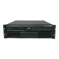
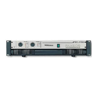
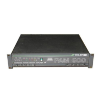
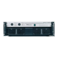
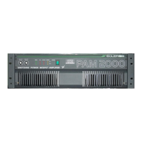
Overview of ECLER's PAM amplifiers and their innovative switching power MOSFET technology.
Guidance on physical placement, rack mounting, and cooling requirements for optimal amplifier performance.
Details on power supply requirements, voltage compatibility, and mains wiring color conventions.
Explanation of the Earth Link switch function for preventing ground loops and hum.
Instructions for connecting balanced and unbalanced audio signals using XLR connectors.
Information on loudspeaker connections using Speak-on connectors and bridging mode setup.
Step-by-step guide for powering on the amplifier and the correct audio chain connection order.
How to use input attenuators to safely adjust signal levels and protect loudspeakers.
Explanation of front panel indicators for signal presence, clipping, protection, and thermal status.
Discussion on the performance and limitations of operating the amplifier at a 2 Ohm load.
Details on optional active filter modules for bi-amplification and frequency configuration.
Information on the optional limiter module for distortion control and loudspeaker protection.
Guidelines for safely cleaning the amplifier's front panel to avoid damage.
Detailed technical specifications including output power, frequency response, distortion, and dimensions.
A comprehensive list identifying all front and rear panel controls and connectors by number.
Visual representations of the PAM amplifier front and rear panels with numbered components.
Internal circuit block diagram illustrating the signal flow and key functional modules of the amplifier.
| Power Output | 1000 W |
|---|---|
| Channels | 2 |
| Frequency Response | 20 Hz - 20 kHz |
| Total Harmonic Distortion (THD) | <0.05% |
| Signal to Noise Ratio | > 100 dB |
| Damping Factor | > 200 |
| Input Sensitivity | 1.4V |
| Protection | Short circuit, thermal, overload |
| Connectors | XLR |
| Power Supply | 100-240VAC, 50-60Hz |
| Cooling | Convection |
| Input Impedance | 20 kΩ |