Do you have a question about the Ecler PAM2600 and is the answer not in the manual?
Safety guidelines for mains wiring, earthing, and handling the amplifier to prevent damage or injury.
Guidance on rack mounting, ensuring adequate airflow, and using protective washers for secure installation.
Details on power supply voltage compatibility, consumption, wire color coding, soft start, and fuse specifications.
Explains the function of the Earth Link switch for preventing ground loops and hum in connected audio equipment.
Describes XLR input connectors, pin assignments for balanced/unbalanced signals, and impedance characteristics.
Information regarding the Speak-on output connectors for loudspeakers and bridging mode connections.
Procedure for powering on the amplifier and the correct order for connecting audio chain components.
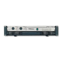
Details on using step-rotative potentiometers to safely adjust input levels and protect loudspeakers.
Explanation of signal, protection, clip, thermal, and bridged mode indicators on the front and back panels.
Discusses the implications of 2-ohm operation on sound quality, efficiency, and thermal protection.
Information on optional active filter modules for bi-amplified systems, configurable as low-pass or high-pass filters.
Details on the limiter module for controlling harmonic distortion by automatically adjusting input signal levels.
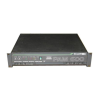
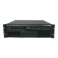
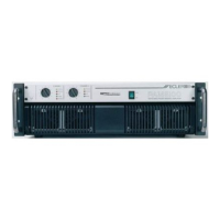
A comprehensive list identifying and numbering all functional components and connectors on the amplifier.
| Channels | 2 |
|---|---|
| THD | < 0.1% |
| THD+N | < 0.1% |
| S/N Ratio | > 100 dB |
| Input Sensitivity | 1.4 V |
| Damping Factor | > 200 |
| Connectors Outputs | Speakon, binding posts |
| Frequency Response | 20 Hz - 20 kHz |
| Input Impedance | 20 kOhms balanced |
| Protection | Thermal, short circuit, DC |
| Cooling | Forced air |
| Connectors Inputs | XLR, TRS |
| Power Consumption (typical) | 1200W |