LIVE Wire : connect to house
wires coloured Brown, Red or
marked with L.
NEUTRAL Wire : connect to
house wires coloured Blue,
Black or marked with N.
INTERCONNECT Wire :
connect to the third wire. If you
are not interconnecting to
other units, do not connect this
wire.
Insert a 9V battery firmly into
battery compartment on the
rear of the alarm. NOTE POLARITY OF
CONNECTIONS. Ensure the metal tab is fully depressed
when the battery has been fitted.
NOTE – For the safety of the end user the heat alarm
cannot be fitted without its battery.
Before assembly to base plate test the correct operation of
the heat alarm (operating from the battery only) by
depressing the test button on the front of the alarm
. Th
e unit
should emit a loud pulsating alarm.
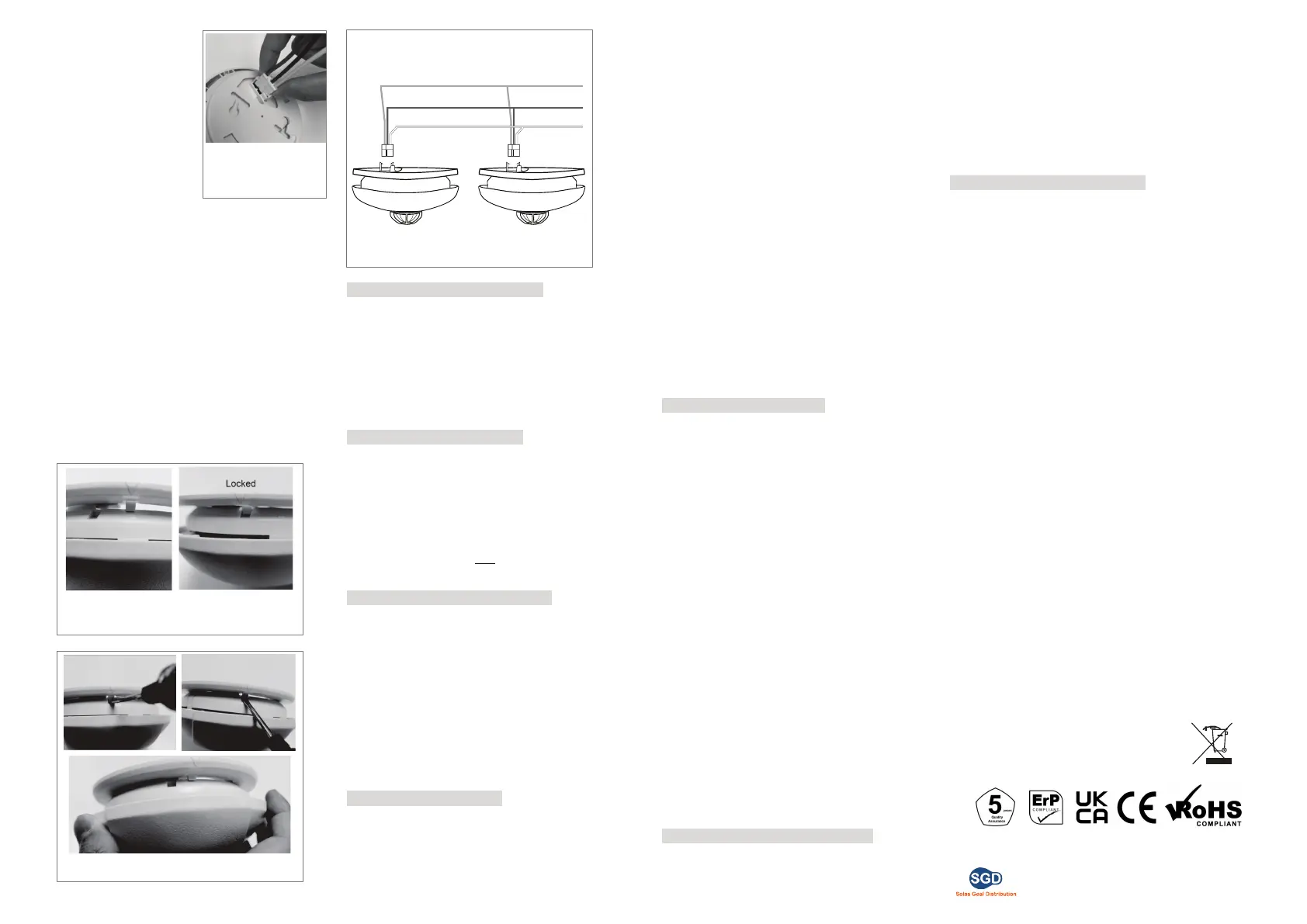
Assemble alarm unit onto the mounting plate by turning the
alarm unit counter-clockwise. See Figure 4
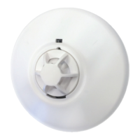
Restore the AC supply by pluging the AC QUICK
CONNECTOR into the back of the alarm (se
e Figure 4).
Make sure that the locks on the connector snap into place.
Test the correct operation of the heat alarm by
depressing the test button on the front of the detector. The
unit should emit a loud pulsating alarm.
Should use 2.1mm wire for connectio
n.
OPERATING YOUR HEAT ALARM
Once the heat alarm has been installed a small GREEN indicator
light (LED) should be visible through the alarm grill indicating that
AC supply is healthy. A RED indicator light (LED) should also flash
approximately once a minute to indicate the battery is healthy and
the unit is operating properly.
When the Heat Alarm sen
ses temperature above 60ºC (plus or
minus a few degrees), the unit will emit a
loud (85dB) pulsating
alarm until the temperature drops below 60ºC. During the alarm
condition, the RED indicator light (LED) will flash quickly
TESTING YOUR HEAT ALARM
It is recommended that you test your Heat Alarm once a week to
ensure the detector is working correctly.
Push and hold the test button for approximately 3 seconds. A loud
pulsating alarm sho
uld sound and a RED flashing indicator light
(LED) can be seen to indicate the correct function.
NOTE – for multiple interconnected Smoke / Heat Alarms, only the
RED indicator light (LED) of the originating unit will flash rapidly. All
other units in the interconnect system wil
l sound an alarm but their
RED indicator light (LED) will NOT flash. Test each alarm checking
that the alarm is triggered on all other alarms installed.
MAINTAINING YOUR HEAT ALARM
A fresh battery should last for approximately one year. If the Heat
Alarm emits a short ‘beep’ once a minute the battery is at the end of its
life and should be replaced immediately. This low voltage
warning will be given for at least 7 days. If the red indicator light
(LED) does not flash every minute then replace the battery.
Clean your alarm at least once every six month
s to prevent dust
build up. This can be done using a vacuum cleaner with the brush
attachment. Clean gently around the front grilled section and sides.
WARNING : The apparatus shall not be exposed to dripping or
splashing and no objects filled with liquids, such as vases, shall be
placed on the apparatus.
BATTERY REPLACEMENT
Always TURN OFF the A.C. supply to the Heat Alarm before
replacing the battery. Replace the battery at least once annually, or
immediately when the low battery signal sounds once a minute,
even though the Heat Alarm is receiving A.C. power.
Test the alarm for
correct operation using the test facility
whenever the battery is replaced.
WARNING: DANGER OF EXPLOSION IF BATTERY
IS INCORRECTLY REPLACED. THE USE OF BATTERIES
OTHER THAN THOSE RECOMMEND
ED ON THE BACK OF
THE HEAT ALARM MAY BE DETRIMENTAL TO ITS
OPERATION
The battery should only be replaced by a qualified
electrician or similarly qualified person.
Turn off the A.C. power supply to the Heat Alarm.
Gently unlock the detector unit from the base by push
back the snap lock with a screw driver and turn the alarm
unit clockwise to release it. See Figure 5 and Figure 6
Remove the battery from the compartment.
Insert a new, healthy 9V battery. NOTE POLARITY OF
CONNECTIONS. Ensure the metal tab is fully
depressed when the battery has been fitted
Using the Push-to-Test button, test the heat alarm to verify
9V DC battery back-up. See “TESTING YOUR HEAT
ALARM”
Reattached the heat alarm to the mounting plate by rotating
the alarm unit counter-clockwise until the it snaps into place.
(see Figure 4)
Turn on the AC power and test the Heat Alarm using the
Push-to-Test button. See “TESTING YOUR HEAT ALARM”
IMPORTANT SAFEGUARDS
Installation of your Heat Alarm is only one step in your safety
plan. Other important steps should be taken to further
improve your safety:-
Install the Heat Alarm properly, following this
instruction leaflet
Test your Heat Alarm weekly
Replace the battery immedia
tely once depleted
Do not smoke in bed
Keep matches & lighters away from children
Store flammable materials in
a proper manner and
never use them nea
r naked flames or sparks
Maintain emergency equipment such as Fire
Extinguishers, escape ladders etc and ensure all
occupants know how to use them correctly.
Plan an escape route/s from your building in advance and
ensure all occupants are aware of them. Re-enforce this
awareness periodically through-out the year.
Make sure escape routes remain free of any
ob
structions.
WARNING: IF THERE IS ANY QUESTION AS TO THE
CAUSE OF AN ALARM IT SHOULD BE ASSUMED THAT
THE ALARM IS DUE TO AN ACTUAL FIRE AND THE
DWELLING SHOULD BE EVACUATED IMMEDI
ATELY.
THIS PRODUCT IS A SEALED UNIT AND CANNOT BE
REPAIRED – IF THE UNIT IS TAMPERED WITH IT WILL
INVALIDATE THE WARRANTY. IF THE UNIT IS FAULTY
PLEASE RETURN IT TO YOUR ORIGINAL SUPPLIER
WITH YOUR PROOF OF PURCHASE.
LIMITATIONS OF THE HEAT ALARM
Heat Alarms are not designed to protect life safety
against fire and smoke. In most fires, hazardous levels of
toxics gases and smoke can build up before the
Heat Alarm will operate. In cases where life safety is an
issue, Heat Alarms should only be used to provide an
added source of protection.
Heat alarms cannot provide an alarm if heat does not reach the
alarm. Therefore, Heat Alarms may n
ot sense fires starting in
chimneys, walls, on roofs, on the other side of a closed door or on
a different floor.
Home fires develop in different ways and are often
unpredictable. No one type of alarm is always best, and a given
alarm may not always provide warning of a fire.
YOUR HEAT ALARM WARRANTY
These Heat Alarms are warranty to be free from defects in
materials and workmanships under normal use and service for a
period of five years from date of purchase. The company will not be
obligated to repair or replace parts which are found to be in need of
repair because of misuse, damage or alterations occur after the date
of purchase. Send the Heat Alarm with proof of purchase, postage
and return postage prepaid, to local distributor. The liability of the
company
arising from the sale of this Heat Alarm shall not in any case
exceed the cost of replacement of Heat Alarm and in no case shall
the company be liable for consequential loss or damages resulting from
the failure of the Heat Alarm.
SOLAS GEAL DISTRIBUTION LTD. SHALL HAVE NO LIABILITY
FOR ANY PERSONAL INJURY OR PROPERTY DAM
AGE,
OR ANY
SPECIAL INCIDENTAL, CONTINGENT OR CONSEQUENTIAL
DAMAGE OF ANY KIND RESULTING FROM A FIRE. THE
EXCLUSIVE REMEDY FOR BREACH OF THE LIMITED
WARRANTY CONTAINED HEREIN IS THE REPAIR OR
REPLACEMENT OF THE DETECTIVE PRODUCT AT SOLAS GEAL
DISTRIBUTION LTD. OPTION. IN NO CASE SHALL SOLAS GEAL
DISTRIBUTION LTD.’S LIABILITY UNDER ANY OTHER REMEDY
PRESCRIBED BY LAW EXCEED THE PUR
CHASE PRICE. YOUR
SMOKE
ALARMS IS NOT A SUBSTITUTE FOR PROPERTY,
DISABILITY, LIFE OR OTHER INSURANCE OF ANY KIND.
APPROPRIATE COVERAGE IS YOUR RESPONSIBILITY.
CONSULT YOUR INSURANCE AGENT.
This does not affect your statutory rights.
This alarm is only suitable for single occupancy private
dwellings only and not intended for multi occupancy private
dwellings or commercial or industrial dwellings.
Waste electrical products should not be disposed of with normal
household waste. Please recycle where facilities exist. Check
with your Local Authority or retailer for recycling advice. New
regulation will encourage the recycling of Waste from Electrical
and Electronic Equipment (European "WEEE Directive"
effective August 2005).
Ver: 13-MAY-2017
Figure 5
Turn the alarm uni
ts clockwise until the snap lock
engages.
Figure 6 – Push Back the snap lock and turn the
Alarm anti-clockwise
Figure 4
Plug the AC QUICK
CONNECTOR into the
back of the alarm.
Figure 7 – Wiring & Interconnect facility
Brown - Live
Blue - Netural
White - Interconnect
*20 alarms maximums
*150 meters maximum between first and last interconnected alarm
Unit 7/8 Ashbourne Business Centre, Ballybin Road,
Ashbourne, Co. Meath, A84 YP58, Ireland
Ph: +353 1 835 7447,
Unit 32 Junction One Business Park, Valley Road,
Birkenhead, Merseyside, UK, CH41 7ED
Ph: 0330 551 7000, Web: www.sgd.ie
For more information contact:
 Loading...