Do you have a question about the ECO-WORTHY 5A and is the answer not in the manual?
Warnings about explosive gases generated by lead-acid batteries during operation and the importance of following instructions.
Instructions to follow to reduce the risk of battery explosions, including following marked instructions.
Never smoke or allow sparks or flames in the vicinity of the battery or engine.
Cautions regarding charger use, including intended battery types and avoiding damage to property or persons.
Guidelines for safely handling the charger's cord and plug to prevent damage and electric shock.
Avoid operating the charger in closed-in areas or restricting ventilation.
Ensure someone is within voice range or close enough for aid when working with lead-acid batteries.
Keep plenty of fresh water and soap nearby for cases of battery acid contact.
Wear complete eye protection and clothing protection, avoid touching eyes while working near batteries.
Immediate washing procedures for skin/clothing contact with battery acid, and eye contact with water.
Do not drop metal tools on batteries as it might cause sparks or short-circuit damage.
Remove all metal items (jewelry) when working with lead-acid batteries to prevent short circuits.
Remove grounded terminals first and ensure vehicle accessories are off to prevent arcs during charging.
Ensure the area around the battery is ventilated during charging to disperse explosive gases.
Clean battery terminals carefully, ensuring corrosion does not contact eyes.
Add distilled water to unsealed batteries and follow instructions for sealed batteries.
Determine battery voltage and ensure it matches the charger's output rating.
Place charger as far from battery as DC cables permit, not directly above or below the battery.
Never allow battery acid to drip on the charger when reading gravity or filling battery.
Do not operate the charger in a closed-in area with poor ventilation.
Do not set a battery on top of the charger.
Connect/disconnect DC clips only after removing AC cord; never allow clips to touch each other.
Steps for connecting the charger to a battery installed in a vehicle to avoid sparks.
Stay clear of moving engine parts like fan blades, belts, and pulleys during connection.
Check battery post polarity; positive posts may have a larger diameter than negative posts.
Determine which battery post is grounded to the chassis for correct connection.
Connect red clip to positive post, black clip to chassis of a negative-grounded vehicle.
Connect black clip to negative post, red clip to chassis of a positive-grounded vehicle.
Connect via a permanently mounted eyelet Lead SAE connector if applicable.
Connect the charger's AC supply cord to an electric outlet.
Sequence for disconnecting: AC cord, chassis clip, then battery clip.
Check battery post polarity before connecting when the battery is outside the vehicle.
Attach an insulated battery output cable to the negative battery post.
Connect the positive (red) clip from the charger to the positive battery post.
Connect the negative (black) clip to the free end of the cable, away from the battery.
Position yourself and the cable end away from the battery during final connection.
Connect the charger AC supply cord to an electric outlet.
Disconnect in reverse order of connection, breaking the first connection far from the battery.
Marine batteries must be removed and charged on shore unless special equipment is used.
Charger is automatic; monitors battery and switches to storage mode when fully charged.
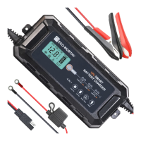
How to connect the red positive and black negative leads to the battery terminals.
Periodically check water levels for lead-acid batteries left connected long-term.
Charger has spark-free and reverse polarity protection; avoid clip contact.
Charger requires at least 2V from battery; correct polarity is needed for charging.
Red 'Reverse Polarity' light flashes if connected incorrectly; re-connect properly.
Avoid repeatedly plugging/unplugging charger; wait 1 minute after unplugging.
Formula and example for estimating battery charge time based on capacity and current.
Recommendation to charge only one battery at a time.
Charger requires >2V to start; a bad battery indicator flashes if below this.
Procedure to momentarily jump a <2V battery to a charged one to initiate charging.
Batteries below 9V after rapid discharge may be defective.
Timer protects marginal batteries from overcharging; switches to float mode if charged within 72 hours.
Press MODE key before connecting to select charge mode: STD, AGM, LI, DC, Low temp.
Explanation of various LCD signals like DC Adapter, battery types, charging voltage, and indicators.
How to select and connect for Standard (GEL, SLA, VRLA) battery charging.
How to select and connect for AGM battery charging.
How to select and connect for LiFePO4 battery charging.
How to select and use the DC Adapter mode for 12V/10A output.
How to select for charging lead-acid batteries in temperatures below -10 degrees.
How to use the charger to test battery health without AC power.
Indications for Power On, STD Mode, AGM Mode, Low Temp Mode, charge processes, GOOD, BAD BAT, BAT LOW, Fault.
Indications for LI mode, charge processes, GOOD, Bad Battery, BAT LOW, Fault for LiFePO4 batteries.
Note on connecting clips and polarity for LiFePO4 battery charging.
LCD signals and indications for DC Adapter mode and Battery Tester mode.
Steps for when there is no LCD signal, checking connections and power.
Steps for when LCD is on but no charging current, checking battery connection and damage.
What BAT LOW signal means (battery voltage under 9V) and potential actions.
What BAD BAT signal means (worn out/defective battery) and suggestions.
Troubleshooting when charging but 20-100% signal doesn't appear, checking battery condition or capacity.
Diagram and description of the LiFePO4 charging stages: PCM Activation, Soft Start, Bulk, Absorption, Full Charge.
Initial constant pulse frequency to activate the battery's PCM before charging.
Applied when battery has a very low initial state of charge to help recovery.
Delivers constant current to the battery, taking it up to 80% of full charge.
Constant voltage applied, with current reduced, until the battery is 100% charged.
Charging is complete; battery can be put into service or left connected.
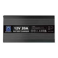
Details on model, input voltage, output voltage, max voltage, and min. starting voltage.
Specifications for overcharge, reverse polarity, short circuit, and spark proof protection.
Specifications for operating temperature and waterproof rating.
Recommended battery capacities for Lead-Acid and LiFePO4 batteries.
Guidance on selecting and applying chargers based on charging and maintenance requirements.
| Output Voltage | 12V |
|---|---|
| Max Charging Current | 5A |
| Operating Temperature | -20°C to 50°C |
| Efficiency | ≥85% |
| Input Voltage | 12-24V |
| Battery Type | Lead-acid |
| Protection | Short Circuit, Reverse Polarity |
| Weight | 300g |