Do you have a question about the EcoNet RETST601SYS and is the answer not in the manual?
Press to access and control connected equipment.
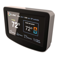
Press the date/time area to adjust.
Shows the current outdoor temperature.
Displays the target temperature for heating or cooling.
Press the mode icon to change the current operating mode.
Access system alarms, alerts, and service contact information.
View current operating status, runtime, and cycle records.
Access control settings for humidity, color, etc.
Adjust the system's time and date from the main screen.
Press up/down arrows to adjust temperature set points.
Select Fan Only mode to control fan speed independently.
Enable or disable following a programmed schedule.
Duration for which temperature changes are effective.
Lock the main screen to prevent unauthorized changes.
Turn the alarm beeper on or off.
Time demand must exist in opposite mode for system to switch.
Minimum difference between heating and cooling set points.
Adjust the displayed room temperature reading.
Select display units in Celsius or Fahrenheit.
System reduces humidity in cooling mode via fan speed and overcooling.
Target relative humidity for dehumidification.
System overcools space to improve dehumidification performance.
Time fan is off to allow water drainage from air handler.
System controls attached humidifier to increase space humidity.
Target relative humidity for humidification.
Choose modes for humidification: heating, fan, or cooling.
Automatically adjusts humidity based on outdoor temperature.
Select day and touch time/set points to modify schedule.
Use copy/paste functions to duplicate schedules.
Thermostat starts recovery early to reach set point on time.
Program vacation mode by setting date, time, and set points.
Toggle vacation mode on or off using screen text.
Select desired color and press accept to change background.
View operating status, cycles, and run times for furnace or AC/HP.
Service icon blinks/beeps for maintenance reminders or equipment alarms.
Follow all instructions carefully to avoid personal injury or property damage.
Disconnect power to units before beginning installation.
Ensure all wiring adheres to national, local, and state codes.
Properly dispose of old controls containing mercury; EcoNet has none.
Mount 5 ft from floor, in used rooms, on inside walls.
Avoid direct light, heat, airflow, poor circulation, or walls with pipes.
Use 18 AWG or larger wire for reliable connections.
Wire units in a daisy chain, not a star configuration.
Adhere to maximum wire lengths between controls and system ends.
Use shielded wire near high voltage; ground only at indoor unit.
Turn off all power to equipment before starting the mounting process.
Steps to remove old controls and disconnect wires.
Pass wires through backplate, level, and mark wall for mounting holes.
Properly dispose of old controls containing mercury; EcoNet has none.
Use screws and anchors to firmly attach the backplate plastic.
Match and connect wires to backplate terminals by color.
Push excess wire back and seal hole to maintain proper operation.
Align control holes with plastic guides and push to secure.
Let the EcoNet system manage humidification instead of a separate humidistat.
Set type, stages, and size for non-communicating outdoor units.
Adjust furnace LED diagnostic display orientation for readability.
Set duration for blower operation after heating cycle completion.
Adjust airflow for the furnace's high heating stage.
Adjust airflow for the furnace's low heating stage.
Control fan speed when G terminal is activated for accessories.
Set AUX #1 input as Normally Open or Closed for system activation.
Indicate if electric strip heaters are installed in the air handler.
Choose from four airflow options for electric heat.
Set AUX #2 input as Normally Open or Closed for system activation.
Select unit type, stages, and size for non-communicating units.
Reduce compressor speed to lower noise or blower airflow.
Adjust airflow for cooling and heat pump heating modes.
Choose primary heat source for dual fuel systems.
Set outdoor temp above which furnace will not operate.
Set outdoor temp below which heat pump will not operate.
Service icon blinks/beeps indicating an active equipment alarm.
Configure and manage maintenance alerts and reset timers.
Enter and manage servicing contractor phone numbers.
| Brand | EcoNet |
|---|---|
| Model | RETST601SYS |
| Category | Network Router |
| Language | English |