27
Installing the Motherboard
ATX4P1: Auxiliary Power Connector for Graphics Interface
Pin Signal Name
4 +12V
3 GND
2 GND
1 NC
Make sure to connect a 4-pin ATX power cable to ATX4P1; otherwise,
the system will be unstable.
ATX12V: ATX 12V Power Connector
Pin Signal Name
4 Ground
3 Ground
2 Ground
1 Ground
Pin Signal Name
5 +12V
6 +12V
7 +12V
8 +12V
SPK: Internal speaker
Pin Signal Name
1 VCC
2 Key
3 NC
4 Signal
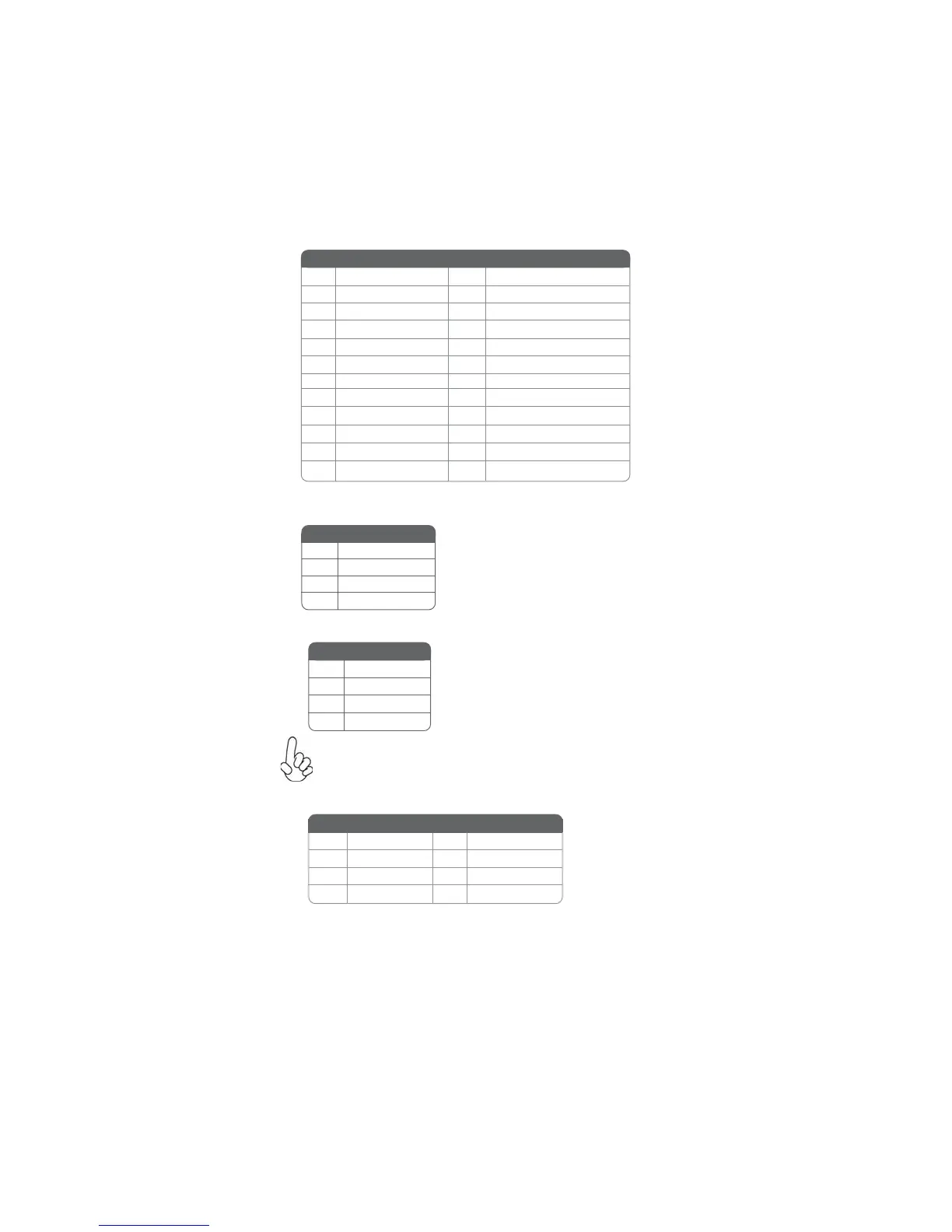
ATX_POWER: ATX 24-pin Power Connector
1 +3.3V 13 +3.3V
2 +3.3V 14 -12V
3 Ground 15 COM
4 +5V 16 PS_ON
5 Ground 17 COM
6 +5V 18 COM
7 Ground 19 COM
8 PWRGD 20 -5V
9 +5VSB 21 +5V
10 +12V 22 +5V
11 +12V 23 +5V
12 +3.3V 24 COM
Pin Signal Name Pin Signal Name
 Loading...