10
English
Step 4. Connecting Cables and Power Connectors:
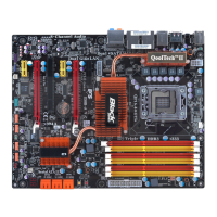
c. Connect 24-pin power cable
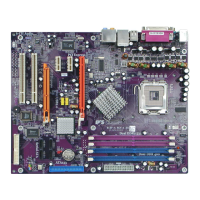
b. Connect SATA power connector to the
SATA device
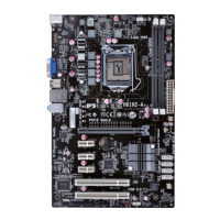
Once the steps above have been completed, please connect the peripherals such
as the keyboard, mouse, monitor, etc. Then, connect the power and turn on the
system. Please install all the required software.
Step 5: Connecting ports on the case:
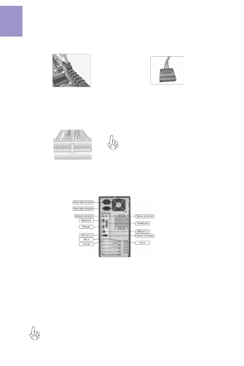
a. Connect the SATA hard drive to its
SATA cable
Please note that when installing 24-pin
power cable, the latches of power cable
and the ATX connector match perfectly.
The sequence of installation may differ depending on the type of case and
devices used.
Using BIOS
The BIOS (Basic Input and Output System) Setup Utility displays the system’s
configuration status and provides you options to set system parameters. When
you power on the system, BIOS enters the Power-On Self Test (POST) routines,
please press <DEL> or F2 to enter setup. When powering on for the first time, the
POST screen may show a “CMOS Settings Wrong” message. Please enter BIOS and
choose “Load Default Settings” to reset the default CMOS values. (Changes to
system hardware such as different CPU, memories, etc. may also trigger this
message.)
VGA port(real panel I/O) + DC_IN
port(real panel I/O) and DP port (real
panel I/O) + ATX_POWER header(internal
I/O header) are alternative options of the
motherboard.