2 / 4 P/N 270492-EN • REV 04 • ISS 10JUL14
Jumper settings
For circuits configured as NACs, the NAC pairs share a
common power/signal source. Two jumpers on the module
select the signal source for each NAC pair. See Figure 2 for
jumper pin numbers.
Notes
• Jumper positions must be set in parallel. Set jumpers in
both JP1 and JP2 the same. Set jumpers in both JP3 and
JP4 the same.
• Jumpers have no effect when the IDC/NAC circuits are
configured as IDC circuits.
Table 1: Jumper settings for circuit power/signal source
[1] Supplied via NAC IN terminals.
[2] See total current limit in “Specifications” on page 3.
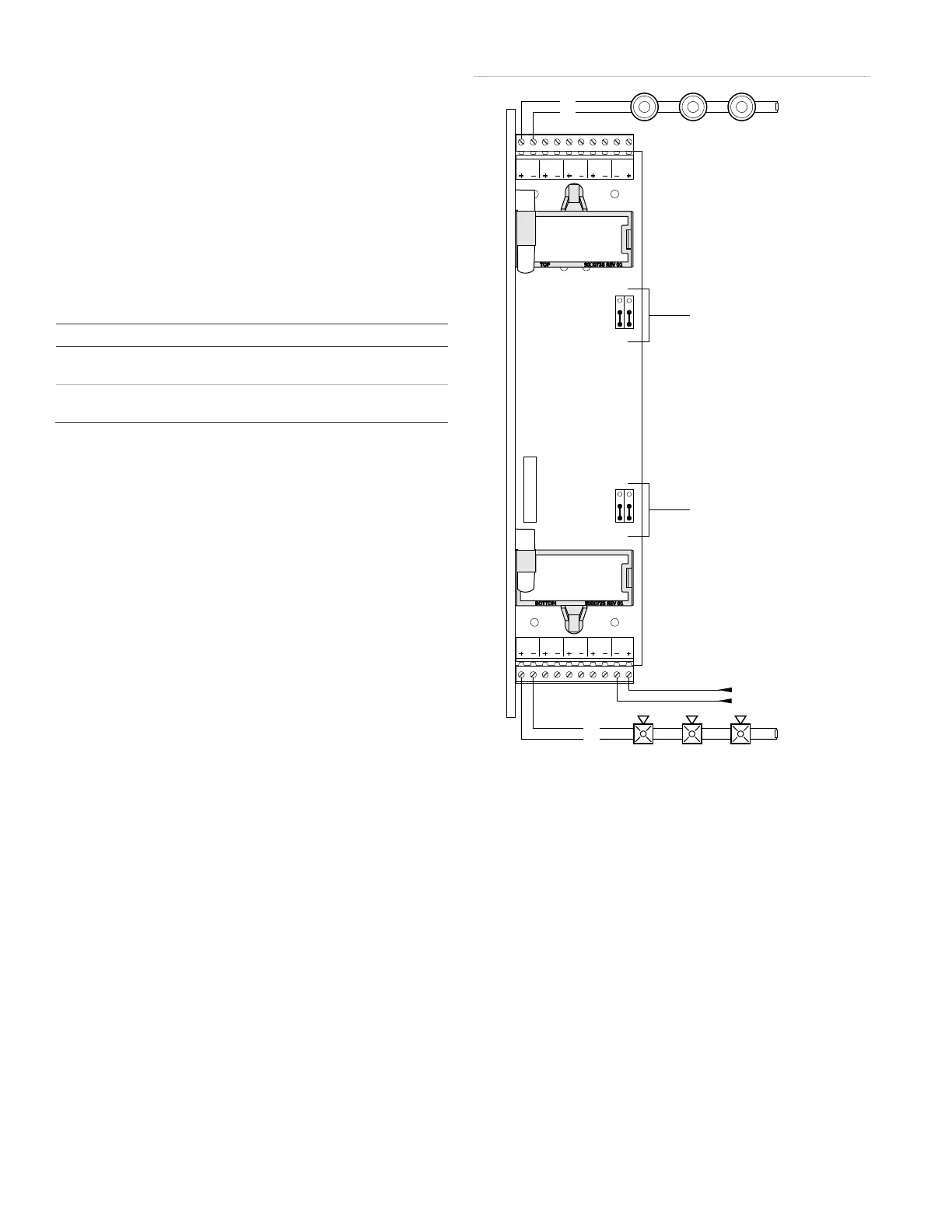
Wiring
Connect field wiring as shown in Figure 2.
• Wiring is supervised and power-limited.
• Maintain 0.25 in. (6 mm) separation between power-
limited and nonpower-limited wiring at all times. Route the
power-limited wiring through the notches at the right front
of the chassis. Secure the wiring to the cabinet using
nylon cable ties.
• If shielded cable is used, it must be continuous, free from
earth ground, and must only be connected to the ground
terminal on the source of the riser.
• Dedicated initiating device circuits (Class B, Style B):
IDC3, IDC4, IDC7, IDC8.
• Circuits configurable as IDC or NAC (Class B, Style Y):
IDC/NAC1, IDC/NAC2, IDC/NAC5, IDC/NAC6.
• Synchronized operation of Genesis strobes requires a
separately installed synchronization device. See the
control panel or power supply compatibility list for
compatible synchronization devices.
• For a list of 3-IDC8/4 compatible devices, see the EST3
Compatibility List (P/N 3100427-EN) and EST3X
Compatibility List (P/N 3101801-EN).
Figure 2: Wiring the 3-IDC8/4
Legend
(1) IDC/NAC1 configured as an IDC circuit (use a UL/ULC Listed
4.7 kΩ EOLR)
(2) Jumper JP1 and JP2 (NAC1 and 2)
(3) Jumper JP3 and JP4 (NAC5 and 6)
(4) From external source
(5) IDC/NAC5 configured as an NAC circuit (use a UL/ULC Listed
15 kΩ EOLR)
Note: Signal polarity is shown in supervisory mode. For an NAC, the
polarity reverses when the circuit is active.
J1
IDC/NAC
1
IDC/NAC
2
IDC
3
IDC
4
NAC IN
1/2
IDC/NAC
5
IDC/NAC
6
IDC
7
IDC
8
NAC IN
5/6
TX RX
15 k
EOLR
Ω
4.7 kΩ
EOLR
+
−
+
−
(1)
(5)
(4)
(2)
(3)
JP4
JP2
JP3
JP1
TB2
TB
1
1
1
1
1
2
2
2
2
3
3
3
3
 Loading...