P/N 270495-EN • REV 06 • ISS 10JUL14 3 / 4
To connect the mains power wiring:
1. Ensure that the mains AC circuit is de-energized.
2. Connect the mains AC conductors from the dedicated mains
distribution circuit to TB1 on the power supplies (see Figure 4).
3. Secure the power supply cover to the standoffs on the top edge of
each power supply.
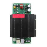
Figure 4: Mains power wiring
Auxiliary 24 VDC riser wiring
Connect the 24 VDC auxiliary power riser conductors to TB1 on the
power supply monitor module as shown in Figure 5.
Note: Current loads must be evenly distributed across all power
supplies.
Figure 5: 24 VDC riser wire connections
Standby battery wiring
Connect the standby batteries to TB2 on the heat sink assembly as
shown in Figure 6 and according to the following requirements:
• Each set (pair) of batteries must be connected to a separate
battery charging circuit, either on a 3-PPS/M(-230) or on a
3-BBC/M(-230).
• Each power supply must be connected to only one set of batteries.
A 3-PPS/M(-230) and a 3-BPS/M(-230) can be wired to the same
set of batteries, as well as a 3-BBC/M(-230) and a 3-BPS/M(-230),
but never a 3-PPS/M(-230) and a 3-BBC/M(-230).
• Each power supply must have its own separate pair of wires
connecting it to a set of standby batteries. Daisy chaining battery
connections from power supply to power supply is not allowed.
• All battery wiring must be the same length and wire gauge.
• All batteries connected to the same control panel must have the
same ampere-hours rating, be from the same manufacturer, and
have the same manufacturing date code.
• Batteries greater than 17 Ah and any additional batteries must be
installed in an external battery cabinet.
• If an external battery cabinet is used to house standby batteries,
the cabinet must be installed within three feet and in the same
room as the control panel.
Figure 6: Standby battery wire connections
Table 1 lists typical battery and power supply combinations.
TB1
H
G
N
TB1
120 VAC
L1
G
L2
230 VAC
H
G
N
TB1
120 VAC
L1
G
L2
230 VAC
Dedicated 120 V or 230 V mains
power distribution circuit
Primary power supply Last booster supply
in the same cabinet
TB1
AUXILIARY POWER
1 2
AUXILIARY POWER
1
2
24 VDC
0 VDC
24 VDC
0 VDC
TB1
TB2
BATTERY TEMP
MON
Not used
To plus and minus terminals
on cabinet battery or to plus and
minus terminals on power
distribution bus in remote cabinet
+ −
−
+
TB2
 Loading...