P/N 3100152-EN • REV 11 • ISS 16MAR17 3 / 6
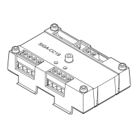
Figure 3: Wiring diagram for NAC (personality code 5 and 25)
(1) Signal polarity is shown when the circuit in supervisory state.
Polarity reverses when the circuit is active.
(2) Supervised.
(3) Power-limited, unless connected to a nonpower-limited source. If
the source is nonpower-limited, eliminate the power-limited mark
and maintain a minimum of 0.25 in. (6.4 mm) space from power-
limited wiring. For other mounting methods, see enclosure and
bracket installation sheets to maintain separation of power-
limited and nonpower-limited wiring. The wire size must be
capable of handling fault current from nonpower-limited source.
— or —
Use type FPL, FPLR, FPLP, or permitted substitute cables,
provided these power-limited cable conductors extending beyond
the jacket are separated by a minimum of 0.25 in. (6.4 mm)
space or by a nonconductive sleeve or nonconductive barrier
from all other conductors. Refer to the NFPA 70 National
Electrical Code for more details.
(4) For synchronized signals you must use synchronized temporal
horn/strobes and personality code 25. Any other combination
will not produce synchronized signals.
(5) 47 kΩ EOLR.
(6) Signaling line circuit (SLC) to next device.
(7) AUX riser (to next module or riser supervisory device).
(8) Power-limited regulated, power supply UL/ULC listed for fire
protective signaling systems.
(9) AUX riser (from previous device).
(10) Signaling line circuit (SLC) from previous device. Supervised
and power-limited.
(6)
+
+
(7)
+
+
(1)(2)(3)(4)
3
8
(9)
(10)
+
(5)
 Loading...