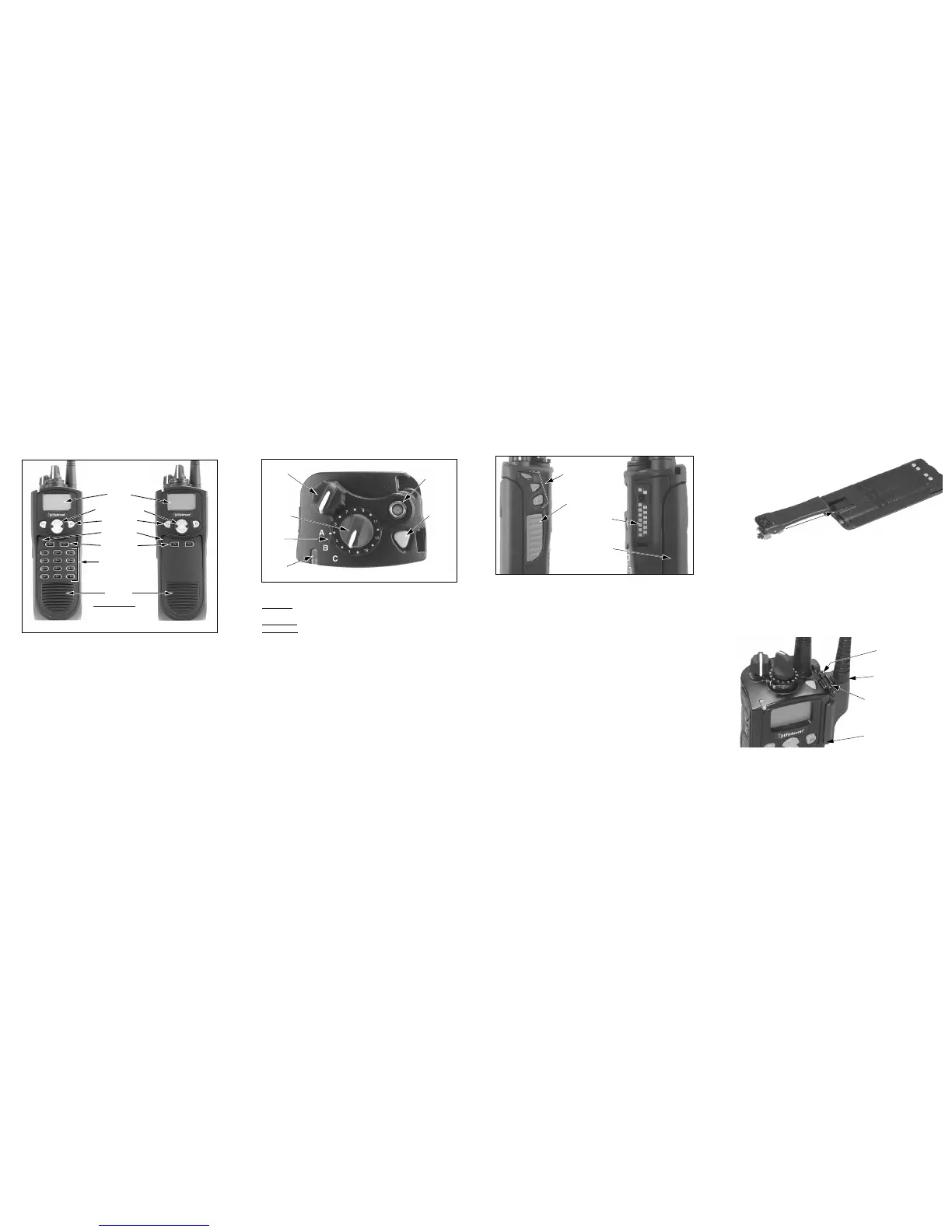
FRONT PANEL CONTROLS
Microphone—The location of the microphone is shown above. For best
results, hold the transceiver 2-3 inches from you mouth and speak at a
normal conversational level.
Display—A graphical LCD (Liquid Crystal Display).
Up/Down Button—Selects zones when multiple zones are programmed.
Also provides up/down select in other modes such as the menu mode.
Pressing the upper part of the button increases the selected number and
pressing the lower part decreases the selected number.
F1—Functions as a Back and Exit button in various modes such as the
Menu Mode. If Menu Mode is not used, this is a programmable option
button.
F2—Selects the Menu Mode and functions as an Enter button. If Menu
Mode is not used, this is a programmable option button.
F3, F4—Programmable option buttons.
DTMF Keypad—The full keypad DTMF models include the 0-9,
*
, and
#
keys which are used to dial telephone, unit ID, group ID, and other numbers.
Speaker—The speaker is located behind this grill. When a speaker/micro-
phone is used, this speaker is automatically disabled.
TOP PANEL CONTROLS
Multi-Function Indicator—Indicates the following conditions:
Stead
y Red–Transmitter keyed (enabled) by pressing the PTT switch on
the side.
Flashing Red–Low battery in receive mode.
Stead
y Green–Signal detected in receive mode.
On-Off/Volume—Turning the knob clockwise turns power on and sets the
volume level. Turning it counter-clockwise to the click turns power off.
Channel Switch—This 16-position switch selects up to 16 channels in the
current zone. Some positions may be unprogrammed in which case a tone
sounds and “UNPROGRAMD” is displayed. Additional zones can be
programmed to allow up to approximately 512 channels to be selected by
this switch.
Rotary Option Switch—This is a three-position switch that can be
programmed to control an option. The “A” position is “on” and the “B” and
“C” positions are “off”. If this switch is programmed to select zones, “A”
selects Zone 1, “B” Zone 2, and “C” Zone 3, if applicable.
Antenna Connector—Connection point for the antenna. Make sure the
antenna is tight before using the radio.
Emergency Switch—This button can be programmed as an Emergency
switch or for other functions. If used as an emergency switch, consult you
system operator to determine how it is used in your radio system.
SIDE CONTROLS
PTT (Push-To-Talk) Switch—This switch is pressed to turn the
transmitter on so you can talk and then released to listen. Transmitting is
indicated when the top panel indicator is red.
Option Switches 1, 2, and 3—Each of these switches can be system
operator programmed to control a specific function.
Battery—Refer to “Battery Removal/Installation” for more information.
Accessory Connector—Connection point for optional accessories such as
a speaker/microphone or earphone. Refer to “Accessory Installation” for
more information.
ZONE AND CHANNEL SELECT
Zone Select—The Up/Down switch is used to change the zone when not
in special modes such as the menu mode. Press the upper part of this
switch to select the next higher number and press the lower part to select
the next lower number. After the highest programmed zone is displayed,
wrap-around to the lowest programmed zone occurs and vice versa.
Channel Select—Channels are selected by the rotary 16-position selector
switch on the top panel. The selected channel number and alias are
indicated in the display. When an unprogrammed channel is selected,
“UNPROGRAMD” is displayed and a tone sounds (if tones are enabled).
BELT CLIP INSTALLATION
Remove the battery and slide the belt clip into the slot on the
battery as shown below. To remove the clip, simply
slide it out. It is held in place by the chassis
when the battery is installed on the
radio.
ACCESSORY INSTALLATION
To connect an accessory such as a speaker-microphone to the transceiver,
proceed as follows:
1. Remove the protective cover over the accessory jack on the side of the
transceiver.
2. Insert the hook on the lower end of the accessory connector into the slot
on the side of the transceiver.
3. Rotate the latch open, press the connector against the transceiver, and
then release the latch to lock the connector in place.
4. Install the included locking screw in the latch tab in the location shown.
OPERATING MANUAL
A complete operating manual on a CD-ROM is available for this radio.
Contact your system operator to obtain this manual.
 Loading...