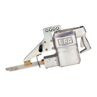
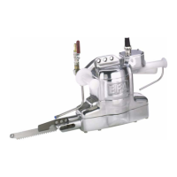
EFA band saws Operating instructions EN
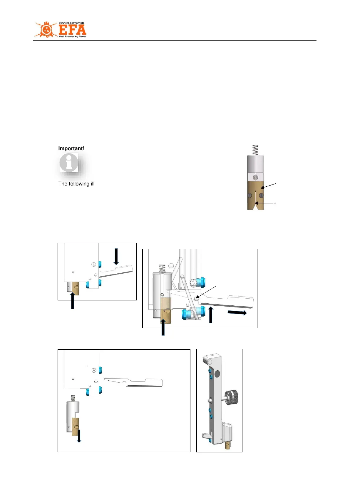
Gap new 0.6 mm
(gap max. 2 mm)
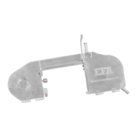
The saw band guides include the following parts, see Fig. 7.2 Saw band guide.
Carbide plate (a) – Support of the sawing pressure
2 carbide rods (b) – Deflection and guidance of the saw band
Compression spring (c) – Spring-loaded support of the sawing pressure
Fibre guide (d)
Carbide plate (a) can be turned over after wear (scoring) (can be used on four sides).
Timely turning prevents cracking of the saw band back.
The carbide rods (b) are not adjustable. They can be used by twisting around on the entire circumference at
the bottom and top. If worn, install new rods. This prevents cracking and guarantees correct sawing.
The saw band guide must be movable.
The fibre guide (d) must be checked regularly for wear and replaced if necessary.
Guide change
Important! If the gap of the fibre guide is larger than
2 mm, it must be changed.
The following illustrations describe how to disassemble the complete guide
unit, lever, holder and fibre guide, which is responsible for guiding the saw
band, for possible maintenance work. For clarity, disassembly is shown only
on the bar. The removal can also be carried out on the bar mounted on the
saw.
Open the cover (A) and remove the saw band from the guide, see
section 7.1.1 Removal of saw band.
Fig. 7.3 – Changing guide
Rear bar
Push lever down (1)
Guide moves upwards (2)
Hold guide up (3)
Remove lever upwards
from holder (4)
Remove lever from bar
(5)
The guide can be removed downwards
Fibre guide (6) and lever (7) are now
removed
The two parts can now be inspected for wear
and, if necessary, worn parts can be
replaced!
Front bar
The same work steps can be
carried out on the front bar of the
splitting saw to carry out any
maintenance operations.
Assembly is carried out in
reverse order!