This document is an Installation, Operation & Maintenance Manual for Ernst Flow Industries' 300-400 Series Valves, specifically designed for liquid level gauging applications.
Function Description
Ernst Flow Industries™ valves are robust instruments engineered to provide accurate liquid level readings for vessels. They are designed to be installed between a vessel and a liquid level gauge, acting as shut-off valves and incorporating safety features. The primary function of these valves is to allow the user to observe the liquid level in a vessel through an attached gauge, while also providing protection against product loss and injury in case of gauge glass breakage.
The valves feature an automatic ball check mechanism. In normal operation, with the valve stem in the fully open position, the ball check is disengaged, allowing fluid to flow freely between the vessel and the gauge. If a gauge failure (such as a gasket or glass rupture) occurs, rapid flow of fluid from the vessel to the gauge will cause the ball check to seat, thereby isolating the gauge from the vessel and preventing further fluid loss.
The valve stem has an extended needle feature. In the closed position, this needle extends through the valve seat, preventing the ball check from sealing. In the open position, the needle retracts, allowing the ball check to operate. This design also allows the operator to dislodge a seated ball check by closing the valve, pushing the ball off its seat with the needle, and then reopening the valve.
Important Technical Specifications
The manual covers two main series: the 300 Series and the 400 Series. While specific pressure and temperature ratings are not detailed in the provided pages, the manual emphasizes that these ratings (found on the nameplate) must meet application specifications. Material compatibility with both process fluid and the surrounding atmosphere is also crucial.
The valves are not to be used for gauging lethal substances as defined by ASME Section VIII.
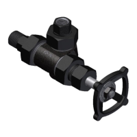
Key components mentioned include:
- Union Tank Connection: For connecting to the vessel.
- Union Gage Connection: For connecting to the liquid level gauge.
- Stainless Steel Ball Check: The safety mechanism that seats to prevent fluid loss during gauge failure.
- Stainless Steel Stem: The operating rod for the valve, featuring an extended needle.
- Stainless Steel Sleeve (400 Series): A component of the valve assembly.
- Integral Bonnet (300 Series): A design feature of the 300 Series.
- Packing Gland: Contains the packing material around the stem to prevent leakage.
Usage Features
- Installation:
- Valves should be connected and mounted in a way that prevents piping strains. They should not support the piping.
- Support brackets are recommended for level gauges over four feet in length or over 100 pounds in weight, especially in vibrating environments, to prevent overloading the valves.
- Shut-off valves are always required between the gauge and the vessel. Ernst Flow Industries™ automatic ball check valves are specifically recommended for this purpose to protect against injury and product loss if glass breakage occurs.
- Operation:
- During operation, the valve stem must be in the 100% open position to ensure the ball check can seat properly in case of a gauge failure. A partially open valve will prevent this automatic seating.
- Commissioning Procedure:
- Open the top isolation valve 1/4 to 1/2 turn counterclockwise.
- Repeat for the bottom isolation valve.
- Visually observe the level in the gauge and allow it to reach equilibrium.
- Open the top valve 100% (until the handle stops rotating).
- Repeat for the bottom valve.
- Opening Valves: Valves should be cracked open carefully, and time allowed for equipment to warm up and/or pressure to equalize before fully opening. Rapid opening can cause glass breakage and injury.
- Dislodging Ball Checks: If a ball check seats, it can be dislodged by closing the valve. However, primary block valves should be closed first, and the ball check valves closed as rapidly as possible, as there is a brief period where fluid can pass through before the stem contacts the seat, posing a risk of injury or fire with hazardous liquids.
- Shipment Protection: Valves are shipped with the packing gland loosened and the stem in the open position. The stem and packing should be adjusted after installation, tightening only enough to stop leakage without causing excessive binding.
- System Shutdown: It is best to leave shut-off valves open during system shutdown to allow the equipment to cool and depressurize. Closing valves can trap high-pressure liquid.
Maintenance Features
- Pre-Maintenance Safety: Before any disassembly, ensure valves are relieved of all internal pressure, ambient temperature, and drained/purged of fluids. Failure to do so can result in sudden pressure release, injury, or fire.
- Replacing Stem Packing (300-400 Series Valves):
- Close valves and drain fluid.
- Disengage the packing gland nut and pull the packing gland out of the stuffing box.
- Remove old packing and insert new packing.
- Re-position the packing gland and nut, then tighten the nut enough to stop leakage without binding the stem.
- Replacing Valve Seat (400 Series Valves):
- Close valves and drain fluid.
- Disengage the sleeve nut from the valve body.
- Remove the stem, sleeve, sleeve nut, gland, and gland nut as a single unit.
- Use a standard 5/8" socket wrench to remove the seat.
- Apply lubricant (Molykote "G" or equivalent) to the threads of the new seat to prevent metal seizure.
- Replace the seat and tighten it well to prevent leakage.
- Replace the stem unit in the valve body and tighten the sleeve unit.