3. Rotate the trimmer head to align the slot in
the ange with the shaft-locking hole in the
gear case and insert the provided Allen key
into the aligned holes to act as a stabilizer.
4. Wear gloves. Securely tighten the trimmer
head onto the shaft COUNTERCLOCKWISE
(Fig. 4).
LINE REPLACEMENT
NOTICE: Always use the recommended nylon
cutting line with a diameter that does not exceed
0.120 in. (3.0 mm). Using line other than that
specied may cause the tool to overheat or become
damaged.
WARNING: Never use metal-reinforced line,
wire, or rope, etc. These can break off and become
dangerous projectiles.
1. Remove the power plug or battery pack.
2. Remove the remaining cutting line, if
necessary. Simply pull it out by hand.
3. Cut one piece of cutting line 26 ft. (8m) long.
Insert the line into the eyelet (Fig.5) and
push the line until the end of the line comes
out of the opposite eyelet. Pull the line from
the other side until equal lengths of the line
appear on both sides of the trimmer head.
4. Press and rotate lower cover assembly in the
direction indicated by the arrow to wind the
cutting line onto the spool (Fig. 6).
5. Push down on the trimmer head while
pulling on the lines to manually advance the
line in order to check for proper assembly of the cutting line.
When the cutting line breaks from the eyelet or the cutting line is not released when the trimmer head is
tapped, follow the steps below:
1. Remove the power plug from the string trimmer.
2. Press two release tabs on the trimmer head and remove the lower cover assembly of the trimmer
head by pulling it straight out (Fig. 7a & 7b).
3. Remove the cutting line from the spool.
4. Make sure the spring is in its original
position in the lower cover assembly.
5. With one hand holding the trimmer, use
another hand to grasp the lower cover
assembly and align the slots in the lower
cover assembly with the release tabs. Press
the lower cover assembly until it snaps into
place, at which time you will hear a distinct click sound (Fig. 8).
6. Following the instructions in “LINE REPLACEMENT” to reload the cutting line.
WARNING: Make sure that the release tabs on the spool retainer snap into place or the spool
assembly will come out during operation, which may result in serious personal injury.
OPERATING MANUAL
REPLACEMENT STRING TRIMMER HEAD
MODEL NUMBER AH3810
This Replacement String Trimmer Head is exclusively compatible with EGO POWER+
String Trimmer STX3800, ST1530/ST1530-FC, EGO POWER+ brush cutter BCX3800,
BC3800/BC3800-FC and EGO multi-tool string trimmer attachment STA1500/
STA1500-FC.
DANGER: If the head loosens after it is xed in position, replace it immediately. Never use a trimmer
with a loose cutting attachment. Replace a cracked, damaged or worn out cutting head immediately, even
if damage is limited to supercial cracks. Such attachments may shatter at high speed and cause serious
injury.
WARNING: Always remove the power plug or battery pack from the product when you are
assembling parts, making adjustments, cleaning, or when the product is not in use.
1
Flange
Flange Cover
Slot in the FLange
Drive Shaft
Upper Cover
Spring
Trimmer Line
Lower Cover Assembly
Spool
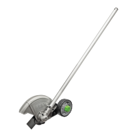
REMOVE THE TRIMMER HEAD
1. Remove the power plug or battery pack.
2. Rotate the trimmer head to align the slot in
the ange with the shaft-locking hole in the
gear case and insert the provided Allen key
into the aligned holes to act as a stabilizer.
3. Wear gloves. Loosen the trimmer head
CLOCKWISE (Fig. 2) until it can be removed
from the shaft.
INSTALL THE NEW TRIMMER HEAD
1. Before installing the new trimmer head,
make sure that the ange is located on the
drive shaft with the bulge facing away from
the gear case and that the ange cover is
closely against the ange with its at surface
facing outward (Fig. 3).
2. Take out the new trimmer head and open
it. Align the drive shaft with the screw
hole of trimmer head, and then pre-
tighten the trimmer head onto the shaft
COUNTERCLOCKWISE.
GUIDE D’UTILISATION
TÊTE DE TAILLE-BORDURE DE RECHANGE
NUMÉRO DE MODÈLE AH3810
Cette tête de taille-bordure de rechange est compatible exclusivement avec les
taille-bordure EGO POWER+ STX3800 et ST1530/ST1530-FC, EGO POWER+ débrous-
sailleuse BCX3800, BC3800/BC3800-FC et attachements de taille-bordure pour
multiples outils EGO STA1500/STA1500-FC.
DANGER : Si la tête se desserre après avoir été xée en place, remplacez-la immédiatement.
N’utilisez jamais un taille-bordure dont un attachement de coupe est mal assujetti. Remplacez
immédiatement toute tête ssurée, endommagée ou usée, même si le dommage est limité à des ssures
supercielles. De tels attachements risqueraient de se fracasser à haute vitesse et causer des blessures
graves.
AVERTISSEMENT : Retirez toujours la che d’alimentation électrique ou le bloc-piles de l’outil
lorsque vous assemblez des pièces, effectuez des réglages, faites un nettoyage ou n’utilisez pas l’outil.
1
Bride de
xation
Cache de la bride de xation
Fente dans la bride de xation
Arbre
d’entraînement
Cache supérieur
Ressort
Ligne de
coupe du
taille-bordure
Ensemble de cache
inférieur
Bobine
RETRAIT DE LA TÊTE DU TAILLE-
BORDURE
1. Retirez la che d’alimentation électrique ou
le bloc-piles.
2. Faites tourner la tête du taille-bordure pour
aligner la fente dans la bride de xation sur
le trou de verrouillage de l’arbre dans la
boîte à engrenages et insérez la clé Allen
fournie dans les trous alignés pour servir de
stabilisateur.
3. Portez des gants. Desserrez la tête du taille-bordure en tournant DANS LE SENS DES AIGUILLES
D’UNE MONTRE (Fig. 2) jusqu’à ce que vous puissiez la retirer de l’arbre.
INSTALLEZ LA NOUVELLE TÊTE DE
TAILLE-BORDURE
1. Avant d’installer la nouvelle tête de
taille-bordure, assurez-vous que la bride
de xation est bien située sur l’arbre
d’entraînement avec la protubérance
orientée dans le sens opposé à celui de la
boîte à engrenages et que le cache de la
bride de xation est placé étroitement contre
la bride de xation avec sa surface plate
orientée vers l’extérieur (Fig. 3).
2. Saisissez la nouvelle tête de taille-
bordure et ouvrez-la. Alignez l’arbre d’entraînement sur le trou de vis de la tête du taille-bordure,
et commencez à serrer la tête du taille-bordure sur l’abre DANS LE SENS CONTRAIRE DES
AIGUILLES D’UNE MONTRE.
3
Flange CoverFlange
Flat surface
facing outwards
Bulge facing from the gear case
Drive Shaft
2
Stabilizer
Trimmer Head
2
Stabilisateur
Tête du taille-
bordure
5
Eyelet
Cutting Line
Lower Cover
6
7b
①
②
7b
Lower Cover
Assembly
Release Tab
8
Release Tab
Slot
4
Stabilizer
Trimmer Head
3
Cache de la
bride de xation
Bride de
xation
Surface plate orientée
vers l’extérieur
Protubérance orientée dans le sens
opposé à celui de la boîte à engrenages
Arbre d’entraînement