Do you have a question about the EGOpro Safe Move 4.0 and is the answer not in the manual?
Proper disposal of electrical equipment and usage limitations for safety.
Defines the primary purpose and application of the EGOpro Safe MOVE 4.0 system.
Explains the meaning of graphical symbols used within the system interface.
Details how the system warns about pedestrian and vehicle proximity.
Explains the system's function for preventing vehicle-to-vehicle collisions.
Instructions for attaching tags to helmets and available accessories.
Step-by-step guide for replacing the tag's battery.
Overview of the system components and general installation guidelines.
Guidance on correctly positioning sensors, CPU, HUB, and display.
Detailed instructions for connecting system components via cables.
Specifics on installing the system using M12 connectors.
Information on adding more sensors to the system using splitters.
Calculation of stopping distances and system activation ranges for safety.
Steps for turning on the system for the first time and initialisation.
Comprehensive guide to configuring sensors via the system menu.
Procedures for checking sensor operation and tag detection.
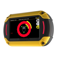
Explanation of the main screen elements and icons.
How the system alerts for pedestrian presence in pre-warning and warning zones.
Monitoring sensor status, HUB diagnosis, and error reporting.
Procedures for driver login, logout, and accessing event data.
Accessing system menus, rebooting, and general configuration options.
Configuring system clock, date, and alarm parameters.
Steps for searching, setting power, and configuring sensors.
Managing user accounts, adding/editing users, and language selection.
Description of optional modules and their status indicators.
How the system alerts for non-active modules.
How the module detects other vehicles and visualizes alerts.
Adjusting sensor power for detecting other vehicles.
Installing the filter module and its function to disable tags.
Connecting the module and configuring its range and auto-login.
Installing badge readers and associating tags with badges.
How the system adapts detection range based on vehicle speed.
Configuring sensor power for normalization and emergency levels.
Installing the aisle module and understanding its status indicators.
Adjusting sensor power for aisle mode and vehicle-vehicle detection.
Installing the Wi-Fi antenna and cellular router for connectivity.
Setting up router username, password, and network parameters.
Enabling remote control and transferring data via Wi-Fi.
Steps for performing pre-operational checks and viewing results.
How to customize checklist questions and upload settings.
Installing the speed sensor and interpreting its status on the display.
Configuring the speed sensor for vehicle movement and direction.
Installing the shock sensor and understanding shock detection visualization.
Configuring sensor thresholds and performing shock sensor tests.
Diagnosing and resolving common system errors and issues.
Periodic checks to ensure system health and proper function.
Guidelines for safely cleaning system components.
Visual representations of how system components are wired together.
Technical details for sensors, HUB, wearable, and helmet tags.
Technical specifications for CPU, display, inhibitor, splitter, and speed sensors.
| Model | EGOpro Safe Move 4.0 |
|---|---|
| Protection | IP65 |
| Operating Temperature | -20°C to 60°C |
| Certifications | CE |
| Features | Real-time alerts |
| Connectivity | Wi-Fi |