15
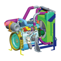
SCHEMATIC DIAGRAM OF LUBE OIL FLOW:
1. Oil Strainer
4B. Bypass valve
8C. Timing gear 15. Auxiliary gallery
2. Oil Pump
5. Main oil gallery
9. Connecting rod bearing
16. Oil jet for piston cooling
2A. Relief valve
6. Engine oil pressure switch
10. Camshaft bushing
17 Piston
3. Oil cooler
7. Bypass filter
10A. Camshaft bushing no.1
18 Con rod bushing
3A. Bypass valve
7A. Restriction orifice
11. Rocker bushing
19. vacuum pump
3B. Regulator valve
8. Crankshaft main bearing
12. Push rod
20. Turbocharger
4. Filter element
8A. Crankshaft main bearing no. 1
13. Tappet
21. Oil sump
4A. Oil bypass alarm
8B. Idler bushing
14. Pressure control valve
22.Fuel Pump
The oil required for lubricating the engine parts is sucked by the oil pump from the sump through the
strainer.
The pressurised engine oil is then sent to oil cooler, where the oil is cooled and then it is sent to the oil filter
for filtration.
The filtered oil is then sent to all engine parts through main oil gallery. By pass oil filter is provided for fine
filtration.
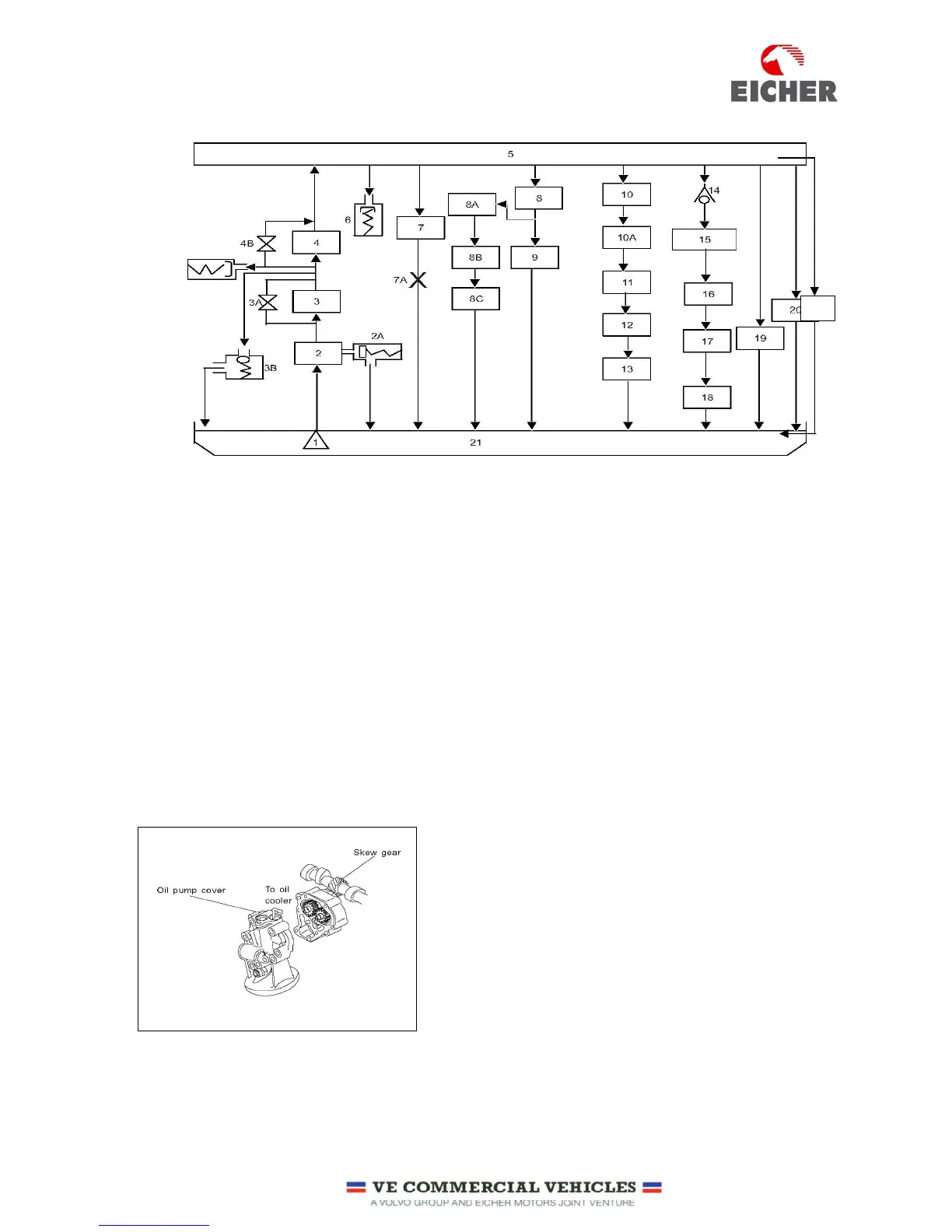
LUBE OIL PUMP:
The oil pump is of gear type and is driven by the skew gear
mounted on the camshaft.
The oil pump cover also serves as the oil filter head, requiring no
oil pipe.
Engine oil is pressurised to the required pressure by the oil pump
and sent to various parts for lubrication and cooling.
 Loading...