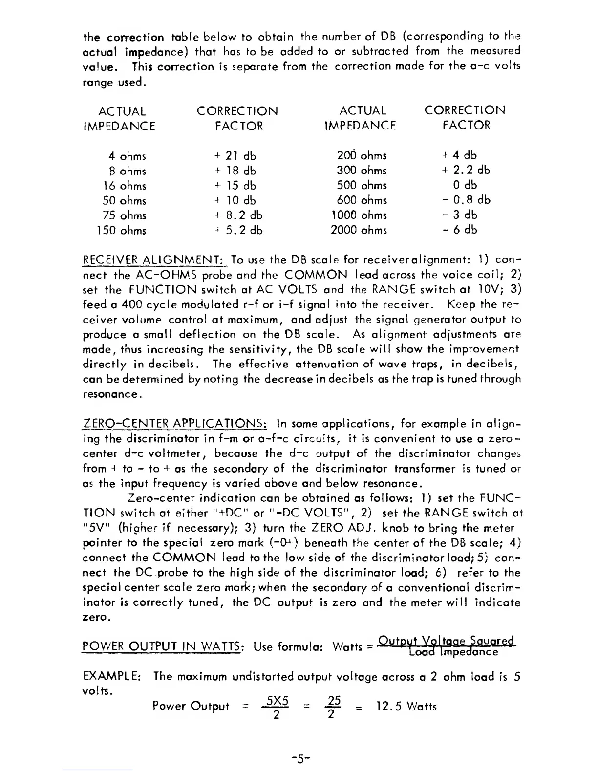
the correction
table below to
obtain
the number
of DB
(corresponding
to the
actual
impedance)
that
has to
be
added
to
or subtracted
from
the
measured
value.
This
correction is separate
from the
correction made
for
the
a-c
volts
range used.
ACTUAL
IMPEDANCE
4 ohms
8
ohms
16 ohms
50 ohms
75 ohms
150
ohms
CORRECTION
FACTOR
+
21
db
+
18
db
+
15
db
+
10 db
+
8.2 db
+
5.2 db
ACTUAL
IMPEDANCE
206 ohms
300
ohms
500 ohms
600 ohms
1000
ohms
2000
ohms
CORRECTION
FACTOR
+
4 db
+
2.2
db
0
db
-
0.8 db
-
3
db
-
6
db
RECEIVER ALIGNMENT:
To
use
the
DB
scale for receiveralignment:
1)
con-
nect
the
AC
~OHM
5
probe
and the
COMMON
lead across
the
voice
coil;
2)
set the FUNCTION
switch
at
AC
VOLTS
and
the
RANGE
switch
at
10V;
3)
feed
a
400 cycle modulated
r-f or
i-f
signal into the receiver.
Keep the
re-
ceiver
volume
control
at maximum,
and
adjust
the
signal
generator output
to
produce a
small deflection
on
the
DB
scale.
As
alignment
adjustments
are
made, thus increasing
the sensitivity, the DB scale
will
show the
improvement
directly
in
decibels.
The
effective attenuation
of
wave traps,
in
decibels,
can
be
determined
by
noting the
decrease
in decibels as the
trap
is tuned
through
resonance.
ZERO-CENTER APPLICATIONS: In some
applications,
for example in
align-
ing the
discriminator in
f-m or
a-f-c circuits,
it
is convenient to
use
a
zero-
center d-c voltmeter, because the
d-c
output
of
the discriminator changes
from
+
to
-
to
+
as the secondary
of the discriminator
transformer
is
tuned
or
as
the
input frequency is varied
above
and below
resonance.
Zero-center indication
can
be obtained as follows:
1)
set the
FUNC-
TION
switch at
either
"+DC"
or
"-DC
VOLTS",
2)
set the
RANGE
switch
at
"5V" (higher
if
necessary);
3)
turn the
ZERO
ADJ.
knob
to
bring
the meter
pointer to
the
special zero
mark (”0+) beneath the
center of the DB
scale;
4)
connect the COMMON lead
to
the
low
side
of the
discriminator load;
5)
con-
nect the
DC probe
to
the
high side
of
the discriminator load;
6)
refer to
the
special center
scale
zero
mark; when
the
secondary
of
a
conventional discrim-
inator
is
correctly
tuned,
the
DC
output is zero and the
meter
will indicate
zero.
POWER
OUTPUT IN WATTS
:
Use
formula:
Watfs
=
-^
u
tp
'
i
mpedance
~
EXAMPLE: The
maximum
undistorted output
voltage
across
a
2
ohm
load Is
5
volts.
Power
Output
=
-
12.5 Watts
-
5
-
 Loading...