is
then applied to the voltage divider.
A d-c voltage, depending on
the
RANGE
switch setting,
is
then applied to
the grid
of
d-c
amplifier
V-2A.
The remaining portion
of
a-c voltmeter
operation is
the same as
the
d-c
volt-
meter operations. The
a-c
circuit
is
also used for decibel measurements
but
the
readings
are
made on
the DB scale.
OPERATION
AS
AN OHMMETER: (See Figures
land
3)
The
circuit
for
opera-
tion as an ohmmeter is
as
follows: The unknown
resistance is
connected across
connectors
J-2
and
J-3. The
FUNCTION switch connects
the
range
voltage
divider
and battery B-l across J-2
and ground.
A
voltage,
depending
on
the
RANGE
switch
setting, is
then
applied to
the
gridof the d-c amplifier V-2A.
The
remaining
portion
of the
ohmmeter
circuit
follows
the same
pattern
as
the
d-c voltmeter
circuit.
POWER
SUPPLY:
(See
Figures 1
and
3)
The operating
potential for the d-c
amplifier
V-2A is
obtained
from the full
wave rectifier
V~3. The B+ output
of
the
rectifier is suitably filtered by
R-l
,
R-2, and C-2. Filament voltages
for all tubes
are
obtained from
the
6.3
volt
winding
of
the power
transformer
T-l
.
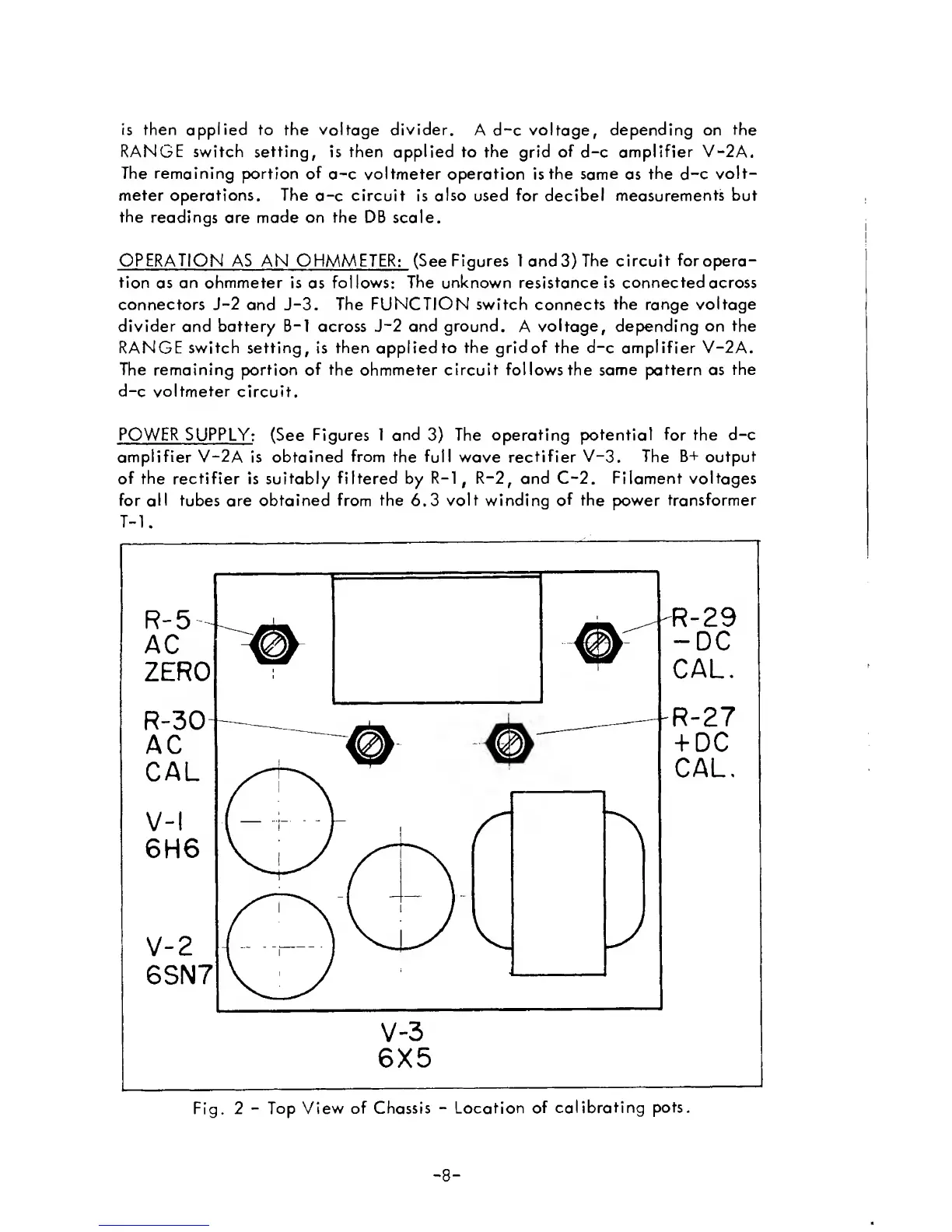
Fig. 2
-
Top
View
of Chassis
-
Location of
calibrating
pots.
-
8
-
 Loading...