EICO
PAGE
3
IMX99
tape it down.
If
the shelf template had been used on the
underside of a stationary shelf, now
place it
on the top-
side
of
the shelf using the marks
on
the rear edge
of
the shelf previously
made. (In the
latter case, accuracy
may be
improved
by
cutting the
two
holes
out of the
shelf-template with
a
razor blade
and then
lining
up
the
holes
in
the shelf
template with the holes in the shelf).
3.
To
use
the panel template, cut it or fold it back
exactly
along the dashed line. This dashed
line
cor-
responds to the junction of the top side of the cabinet
shelf
and
the interior side of the wood panel. Position
the panel template against the interior side
of
the
wood
panel
so that the dashed
line
rests against the shelf
and the two heavy
vertical lines in the panel template
meet with the two heavy
horizontal
lines in the shelf
template. Tape the panel
template
down and use a
center -punch to mark the centers of thefour
3/8"
holes
in
the four corners of the
rectangular
cut-out shown
on the
template.
Now remove both templates and
drill
carefully through each of the four punched centers to
a
hole
diameter of
3/8".
On the frontside of the wood
panel
scribe a
rectangle externally tangential
to the
four
drilled
holes. Check the
height
and width of the
rectangle
against
the panel template dimensions.
These
dimensions
should
not be exceeded. Now
carefully
cut
out the
rectangle with
a sabre saw,
using
a
small blade
to start
accurately in
the
3/8"
holes.
After
the cutting
operation, any
rough
spots
or excess
material along
the edges of
the
cut-out may be
removed
with a file.
Finally, brush
or
blow
out
all
chips and sawdust.
2-4.
MOUNTING THE UNIT
2.
The
outputs
of
the
MX-99 are the
CH.
1
OUT
and
CH.2 OUT
jacks. Connect these to
an
auxiliary
(high level) pair of stereo inputs of
your
amplifier.
Connect the regular
tuner outputs to the amplifier's
regular
tuner inputs. If you
have
the EICO
ST-96 FM-
AM
tuner,
you
may connect the
MX-99 outputs
to
the
MX ADAPTOR jacks MX1 and MX2 and select the ad-
aptor outputs with the tuner SELECTOR switch; the
ST-96
then is connected to the amplifier
as
normally.
3.
Plug
the
line
cord of the
MX-99
into
a
switched
convenience outlet on the tuner.
When the system
is
in operation,
this
plug
may be
oriented
for least audible
hum.
NOTES:
The
MX-99
is designed for
use
with
component-
type
FM (or FM-AM) high
fidelity
tuners of wide-band
design equipped with a multiplex output jack. Not in-
cluded
are non-component type ac-dc equipment (severe
shock hazard), tuners without one or more limiting
stages ahead of the detector (excessive output may
overload
adaptor).
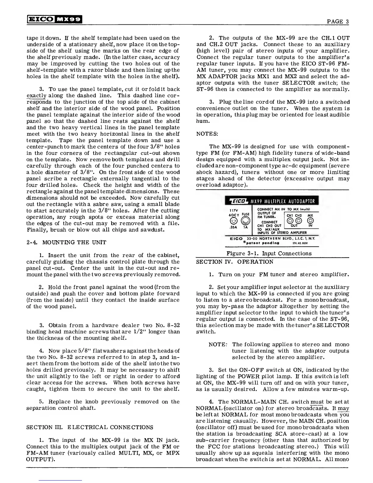
14H-L MX 99
MULTIPLEX AUTODAPTOR
117V
60CY
FUSE
(
2
)
35A 1A
CONNECT MX IN TO MX
(multi)
OUTPUT
OF
CONNECT
CHI CH2
OUT
TO
MX/AUX
INPUTS
OF
STEREO AMPLIFIER
CHI CH2 MX
@@
@
OUT IN
EICO
33-00 NORTHERN
BLVD.,
L.I.C.
1,
N.Y.
*patont pending
STK.N0.n2tl
1.
Insert the
unit from the rear of the cabinet,
carefully guiding the
chassis control plate through the
panel
cut-out. Center
the unit in the cut-out and re-
mount the panel with the two screws
previously removed.
Figure
3-1.
Input
Connections
SECTION
IV.
OPERATION
1.
Turn on your FM tuner and stereo
amplifier.
2.
Hold the front
panel against the wood (from the
outside) and push the
cover and bottom plate forward
(from the
inside) until they contact the inside surface
of the wood
panel.
3.
Obtain
from a
hardware dealer two
No.
8-32
binding head machine screws that are
1/2"
longer
than
the thickness of the
mounting shelf.
4. Now
place
5/8"
flatwashers against
the heads of
the two No.
8-32
screws referred to in step
3,
and in-
sert them from the bottom side
of the shelf
into
the two
holes drilled previously.
It may be necessary to shift
the unit slightly to the left
or
right
in order to afford
clear
access for the screws. When both screws have
caught,
tighten them
to secure the
unit
to the shelf.
2. Set your
amplifier input selector
at
the auxiliary
input to which the
MX-99
is connected if
you
are going
to listen to a stereo broadcast. For a mono broadcast,
you may by-pass
the adaptor altogether
by
setting the
amplifier input selector to the input to which the tuner's
regular output is connected. In the case of the
ST-96,
this selection may be made
with
the tuner's SELECTOR
switch.
NOTE: The
following applies
to stereo and mono
tuner
listening with
the
adaptor
outputs
selected by the stereo
amplifier.
3.
Set the
ON-OFF
switch at
ON,
indicated by the
lighting of the
POWER
pilot lamp. If this switch is
left
at
ON,
the
MX-99
will turn off and
on
with your tuner,
as is usually desired. Allow
a
few minutes warm-up.
5.
Replace the knob previously removed on the
separation
control
shaft.
SECTION
III. ELECTRICAL
CONNECTIONS
1. The input of the
MX-99
is the
MX IN
jack.
Connect this to the
multiplex
output jack of the
FM
or
FM-AM tuner
(variously called
MULTI, MX, or MPX
OUTPUT).
4.
The NORMAL-
MAIN CH.
switch must be set at
NORMAL (oscillator
on)
for stereo broadcasts. It may
be
left
at NORMAL for most mono broadcasts when you
are listening casually. However, the
MAIN CH.
position
(oscillator
off) must beused for mono
broadcasts
when
the station is broadcasting SCA store-cast) at a
low
sub-carrier
frequency (other
than that authorized by
the
FCC
for
stations broadcasting stereo.) This will
usually show
up
as squeals interfering with the mono
broadcast
when
the switch is set at
NORMAL.
All mono
 Loading...