terminal 1 (Fig. 6) and the other wire to white
terminal 2 (Fig. 6) of the sensor circuit board.
Repeat this process for the red cable by clamping its
wires to red terminals 1 and 2 (Fig. 6). Finally, clamp
the white cable to the terminals marked „white 1“ and
„white 2“ and the red cable to the terminals marked
„red 1“ and „red 2“ as per the terminal diagram found
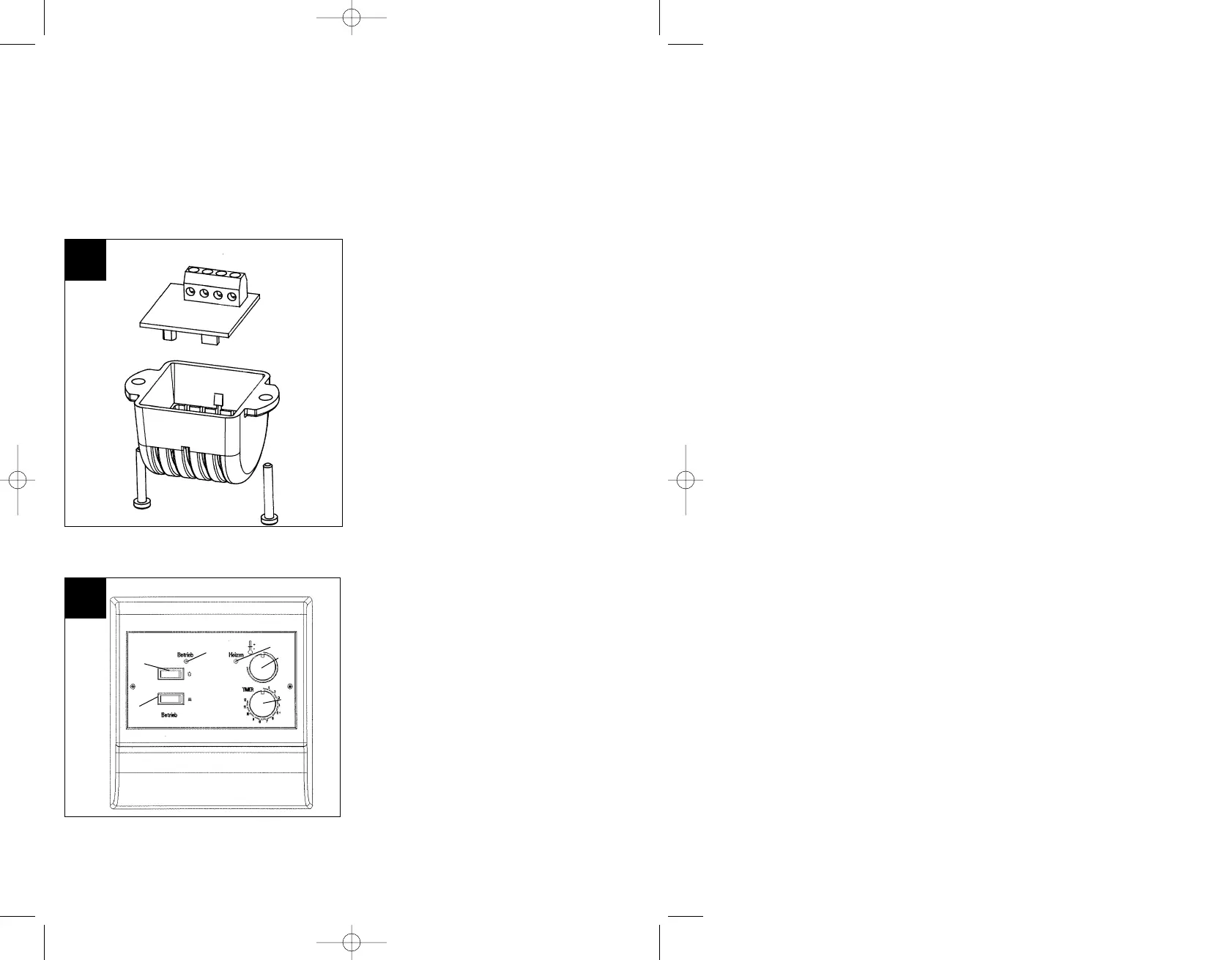
in the controller case. You can now snap the printed
circuit board into the protective case and affix it to
the ceiling with the two 3 x 16 mm screws.
Operation and functions
Refer to Figure 7 for the layout of the operator
controls.
1 = Heater switch
2 = Light switch
3 = Regulator knob for temperatures of
70°C to 110°C
4 = Regulator knob for timer
5 = Standby diode
6 = Heating mode diode
Operation:
Set switch No. 1 to HEAT, which illuminates the
green LED. You can alter the temperature inside the
sauna to the desired temperature using the regulator
knob. Depending on the temperature in the sauna at
the time, the red LED will illuminate to indicate that
heating is in process. Turning the regulator
clockwise increases the temperature; turning the
regulator counterclockwise decreases the
temperature. The controllable temperature range is
between approx. 40°C and 110°C. Please take into
account that the reading you see on the thermometer
in the sauna may deviate from the temperature you
programmed into the sauna controller as the
regulating sensor is located directly in the hot air
current of the heater. However, the regulation
mechanism is configured so that normal spa
temperatures are achieved in the sauna.
Use of the timer:
To set a time when the heating process should
begin, turn the timer regulator knob (Fig. 7, Item 1) to
the desired time interval.
Timer function:
The power switch (Fig. 7, Item 1) must be turned off.
Enter the desired amount of time before heating
begins.
Turn on the power switch [timer activation is signified
by a flashing heat diode (Item 6)].
Note that, for safety reasons, the time can only be
altered when the unit is switched off. Adjusting the
regulator (Fig. 7, Item 4) has no effect on the
previously entered time. If you would like to alter the
previously entered time, you must first turn off the
power switch, change the time, then turn the switch
on again. The time registered when switching the
power on is the new starting time for the timer.
Malfunctions:
If the green operating diode does not illuminate after
switching on, check that all 3 phases contact the 230
V neutral conductor on the incoming wire.
4
7
6
Anleitung ESS 9000-T_GB 24.10.2001 10:04 Uhr Seite 4
 Loading...