GB
- 23 -
lubricating fi lm. However, if the same low viscosity
oil is used during the summer it will become even
thinner due to the ambient temperatures alone,
and as a result the lubricating fi lm could break
down, causing the chain to overheat and become
damaged. In addition, the chain oil would burn
and produce unnecessary pollutants.
Filling the oil tank (Fig. 11):
•
Place the chainsaw on a flat surface.
•
Clean the area around the oil tank cover (Item
31) and then clean the oil tank cover.
•
Fill the tank (Item 30) with saw chain oil. In
the process, make sure that no dirt enters
the tank, as this could cause the oil nozzle to
become blocked.
•
Close the oil tank cover (Item 31).
After the chain saw mounting kit has been fi tted
and when the equipment is not being used, slip
the cutter guard (Fig. 1/Item 14) over the moun-
ted cutter bar with saw chain in order to prevent
injuries.
5.2 d Additional handle (Fig. 12)
Foam rubber grip area (F)
5.3 Using the shoulder strap
Warning! Always use a shoulder strap when wor-
king with the tool. Always switch off the tool before
you release the shoulder strap. Otherwise there is
a risk of injury.
1. Hook the carabiner (Fig. 4/4a/Item A) into the
strap attachment.
2. Slip the shoulder strap (Fig. 14/Item 8) over
your shoulder.
3. Adjust the length of the shoulder strap so that
the strap attachment is at waist level (Fig. 14).
4. The shoulder strap is equipped with a buckle.
Press the hooks together (Fig. 15) if you need
to put the equipment down quickly.
5. To change the strap position on the tool (Fig.
13/Item L), release and adjust the strap at-
tachment on the tube.
5.4 Adjusting the telescopic tube (Fig. 16)
1. Undo the telescopic tube lock nuts (10 + 12).
2. Pull out the telescopic tubes (11 + 13) to suit
the required working height.
3. Secure the telescopic tube lock nuts (10 +
12).
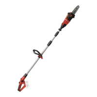
5.5 Fitting the chain saw mounting kit to the
motor head (Fig. 17 – 18)
The cutter rail guard must be slipped over the
mounted cutter rail with saw chain in order to pre-
vent injuries.
Assembly as shown in Fig. 17/18.
The chain saw mounting kit will lock onto the
motor head and is then secured in place. The lock
button (R) will click into place.
5.6 Removing the chain saw mounting kit
from the motor head (Fig. 17 – 18)
The cutter rail guard must be slipped over the
mounted cutter rail with saw chain in order to pre-
vent injuries.
1. Pull the lock button (R) to the left.
2. Undo the assembly nut (6).
5.7 Fitting the battery (Fig. 19 – 20)
Press the side pushlock button (T) of the battery
pack as shown in Fig. 19 and push the battery
pack into the mount provided. When the battery
pack is positioned as in Fig. 20, make sure that
the pushlock button latches in place! To remove
the battery pack, proceed in reverse order.
5.8 Charging the battery (Fig. 20-21a)
1. Take the battery pack out of the equipment.
Do this by pressing the pushlock button (T).
2. Check that your mains voltage is the same as
that marked on the rating plate of the battery
charger. Insert the power plug of the charger
(18) into the mains socket outlet. The green
LED will then begin to fl ash.
3. Insert the battery pack (1) into the battery
charger (18).
4. In the section entitled „Charger indicator“ you
will fi nd a table with an explanation of the LED
indicator on the charger.
The battery pack can become a little warm during
the charging. This is normal.
If the battery pack fails to charge, check:
•
whether there is voltage at the socket outlet
•
whether there is good contact at the charging
contacts.
If the battery pack still fails to charge, send
•
the charging unit
•
and the battery pack
to our customer service center.
To ensure that items are properly packaged
and delivered when you send them to us,
please contact our customer service or the
Anl_GP_LC_18_20_Li_T_BL_SPK13.indb 23Anl_GP_LC_18_20_Li_T_BL_SPK13.indb 23 20.11.2024 14:41:4820.11.2024 14:41:48
 Loading...